Visualise the Invisible Things
Download Materials from here
Select Material
🚧 Computer Networks material is coming soon! Stay tuned.
Please enter your name to continue.
Please enter a valid email address.
Enter your email to receive the material directly in your inbox. Email is optional — you can download without it. You can also share the material with your friends by adding their email IDs here.
100% free • No spam guaranteed
Powered by Druvexaa.com
First Edition
👑Top Pick


Computer Networks Interactive 3D Simulation — Visualizing OSI Layer Functions: How Data Really Travels Across the Seven Layers
Send "Hi" on WhatsApp and follow it in 3D — down your phone's stack, through your home router, across a real WhatsApp server, and back up on your friend's phone. The OSI model names seven layers, but only five header blocks are ever added...


What this simulation actually shows
You type "Hi" in WhatsApp on a phone connected to home Wi-Fi. The simulation follows that message down all seven OSI floors, out through your home router, across the internet to a real WhatsApp server in a Meta data centre, and back up the stack on your friend's phone. Every address, port, sequence number and MAC address shown in the simulation is consistent with every other one — it is a single, coherent scenario rather than seven disconnected textbook examples.
The reason this matters is that the standard classroom diagram — seven layers, seven headers, one neat box per floor — is not what a packet capture looks like. This simulation shows the difference honestly.
Diagram 1 — Seven layers named, four implemented
OSI names seven layers. The Internet Protocol Suite is commonly modelled as four: Link, Internet, Transport and Application. Real protocols are then mapped onto OSI's names, and the mapping does not fit cleanly. In the simulation, Session (5) and Presentation (6) are dimmed and ghosted — the packet crosses those floors and collects nothing.
Why five headers — and not seven, and not four
This is the part almost every explanation gets wrong. It is tempting to say "seven layers minus the two dimmed ones equals five headers." That arithmetic gives the right answer for the wrong reason, because the Physical layer adds no header either. The real accounting is:
- Link adds one — the 802.11 Wi-Fi frame header, plus a trailer.
- Internet adds one — the IPv4 header.
- Transport adds one — the TCP header.
- Application adds two — WhatsApp encrypts the message twice, once with the Signal Protocol for your friend and once with the Noise Protocol for the server.
- Physical adds none — it converts the frame to energy on the medium.
Four layers, five headers. Count the coloured blocks as they appear in the simulation and you will get exactly five, every time.
Diagram 2 — Encapsulation: the packet growing block by block
Notice that the Data Link layer is the only one that adds something at both ends — a header in front and a 4-byte Frame Check Sequence behind, carrying a CRC-32 error check.
Layer by layer, with the real values from the simulation
Layer 7 — Application. WhatsApp builds the message. There is no HTTP anywhere in this app; it uses its own binary protocol, descended from XMPP, on TCP port 443. The Signal Protocol encrypts "Hi" end to end using a Message Key from the Double Ratchet (AES-256-CBC with HMAC-SHA256), and a fresh key is derived for every single message. The result is then wrapped again in a Noise frame (Curve25519, AES-GCM, SHA-256) for the server. Both encryptions happen here, above TCP.
Layer 6 — Presentation. The packet crosses this floor and nothing is added. OSI assigns Layer 6 encoding, compression and encryption; on the Internet the application does all three itself. No Layer 6 header exists in any real packet capture. Learn the layer for the exam; do not look for it on the wire.
Layer 5 — Session. Nothing is added here either. OSI gives Layer 5 the job of managing the dialogue; in reality TCP holds the connection open, and the Noise handshake authenticated your phone once, when it logged in — it does not repeat for every message you type. Sessions are real. A Layer 5 header is not.
Layer 4 — Transport (PDU: segment). TCP adds source port 51344, destination port 443, sequence number 1001, window 64240 and a checksum. "Hi" is tiny, so it travels as one segment. Splitting only begins once the data exceeds the Maximum Segment Size, around 1460 bytes — which is exactly what the "Upload File" button demonstrates.
Layer 3 — Network (PDU: packet). The IPv4 header is added: source 192.168.1.24, TTL 64, Protocol 6 (which is the IANA number for TCP — this is how a packet capture proves the payload is TCP). Total Length is 132 bytes: 20 for IP, 20 for TCP, 92 for the encrypted payload. The routing table has no specific route, so the packet goes to the default gateway at 192.168.1.1.
Layer 2 — Data Link (PDU: frame). The phone is on Wi-Fi, so this is an 802.11 frame, not Ethernet. ARP resolves the router's IP into its 48-bit MAC address. A To-DS frame carries three addresses: RA = BSSID A4:83:E7:2F:11:9C, TA = the phone 4C:1D:96:3A:7B:02, DA = the router's LAN-side MAC A4:83:E7:2F:11:9D. Wi-Fi arbitrates the air with CSMA/CA, and 802.11 will retransmit a lost frame itself — plain Ethernet only detects errors, it does not resend.
Layer 1 — Physical (PDU: bits). The frame becomes nothing but a stream of ones and zeros. On this 5 GHz 802.11ac link that means OFDM with up to 256-QAM. Copper Ethernet uses different line codes entirely by speed — Manchester for 10BASE-T, MLT-3 for 100BASE-TX, PAM-5 for 1000BASE-T. One medium at a time; never Manchester and OFDM together.
Diagram 3 — The real path: what survives and what does not
This is the diagram that classroom slides usually leave out, and it is the reason this simulation exists.
Diagram 4 — Two encryptions, and who can read what
The most common misunderstanding about "end-to-end encrypted" is that the two phones connect directly to each other. They do not. Every message travels to a real server, and that server forwards it. Both phones sit behind NAT on private addresses, so neither can be reached directly from the internet — and your friend's phone may simply be switched off, so the server has to hold the message until it comes back.
So what does end-to-end encryption actually buy you? The server terminates the Noise channel, which means it can see the metadata: who is messaging whom, when, and how much. What it cannot do is read the message, because the Signal ciphertext inside is only decryptable by the recipient's device. End-to-end encryption does not remove the middleman. It makes the middleman blind to the contents.
Six things this simulation corrects
- Encryption is not the Presentation layer. OSI traditionally associates encryption with Layer 6 as a conceptual function. In modern Internet applications it is implemented inside the Application layer. Both of WhatsApp's encryptions happen at Layer 7, above TCP.
- IP addresses do not always survive. Your phone's source address is private. Your home router rewrites it during NAT, so the server never sees it. The common claim that "the IP addresses never change end to end" is false on any home network.
- Layer 2 changes at every hop. Your phone builds an 802.11 frame; your router throws it away and builds a fresh Ethernet frame for the uplink. Same IP packet, different frame, different addresses — every single hop.
- CSMA/CA is Wi-Fi, not Ethernet. Wi-Fi avoids collisions before they happen. Classic Ethernet detected them after (CSMA/CD). Modern switched Ethernet is full duplex and uses neither.
- Small messages are not segmented. "Hi" is two characters. TCP only splits data once it exceeds the MSS, around 1460 bytes. Upload a file in the simulation to see real segmentation.
- The server is a relay, not the destination. Both phones sit behind NAT and cannot reach each other directly. WhatsApp stores the message and forwards it — and because of the Signal layer, it forwards something it cannot read.
"Is this TCP/IP?" — yes, in both senses
"TCP/IP" means two different things and both apply here. As a protocol pair, this message is carried by TCP at Layer 4 running on top of IPv4 at Layer 3 — confirmable on the wire, because the IP header's Protocol field is set to 6. As a reference model, TCP/IP is the four-layer stack, which is exactly why two of the seven OSI floors are dimmed in the simulation.
One qualification worth stating so nobody over-generalises: WhatsApp messaging uses TCP; WhatsApp voice and video calls do not. Calls use UDP with SRTP for the media, because a voice packet that arrives late is already useless — dropping it beats resending it. Media attachments are different again: they are uploaded to and downloaded from a blob store over HTTPS, which is TCP once more. This simulation follows the text-message path.
How to use the simulation
- Beginner Mode — packet, coloured header blocks, a one-line action pill per layer and a live data chip showing the real IPs, ports and MACs.
- Advanced Mode — everything above, plus a full technical panel above each floor with five to six points per layer, separated into sending and receiving.
- Send follows a text message; Upload File shows what changes when data exceeds the MSS; Download File runs the journey in reverse.
- Click any header block, machine, layer floor or server rack to open an inspector showing the real field values. Drag to orbit, scroll to zoom, right-drag to pan.
- Pause and the Speed slider let you freeze on any moment; narration speed is a separate control so the voice stays intelligible at high animation speeds.
A note on the addresses
Public addresses shown come from the ranges reserved for documentation in RFC 5737
(198.51.100.0/24 and 203.0.113.0/24), so no real host is ever implied. Private
addresses, ports, MACs and sequence numbers are realistic examples of what you would see in a packet
capture.

Operating System
RAID: Redundancy, Speed & Data Protection
RAID (Redundant Array of Independent Disks) is a storage technology that combines multiple physical disks into one logical volume. Depending on the level chosen, RAID trades off between raw speed, usable capacity, and the ability to survive a disk failure without losing data...
Explore & Experience Simulation
In the context of the Simulator, the RAID Controller sits between the workstation and the disk array like an invisible traffic manager. Every file you save is split, copied, or mathematically protected before it ever touches a platter, and the operating system never sees any of it — it only sees one clean volume: /dev/md0.
How RAID Works (3 Core Ingredients)
Every RAID level, no matter how complex, is really just a mixture of three building blocks.
- 1. Striping: The controller chops a file into small chunks and spreads them across multiple disks so they can be written and read in parallel — pure speed, zero safety on its own.
- 2. Mirroring:
- Every block is duplicated onto a second disk in real time.
- If one disk dies, its exact twin keeps serving data instantly.
- Costs 50% of total capacity to buy that safety.
- 3. Parity: Instead of a full copy, the controller's XOR engine computes a small mathematical "checksum" block. If a disk is lost, parity plus the survivors can mathematically rebuild the missing data.
RAID Flow — Where Data Goes
Workstation
▶
RAID Controller
(XOR Engine)
▶
Disk Array
/dev/md0
The controller decides — per RAID level — whether each block gets striped, mirrored, or parity-protected before it lands on a physical disk.
Detailed RAID Levels
1️⃣ RAID 0 — Striping (Speed)
Data is striped across all disks with no redundancy. Fastest option, 100% usable capacity — but losing a single disk destroys the entire array.
⚠️ ZERO FAULT TOLERANCE
If any disk fails, every file becomes a corrupted fragment. Never use RAID 0 for data you can't afford to lose.
2️⃣ RAID 1 — Mirroring (Safety)
Every block is written twice, to two separate disks. Reads are fast and a full disk failure causes zero data loss — but you only get 50% of your total purchased capacity to use.
3️⃣ RAID 5 — Striping + Distributed Parity
Data stripes across all disks like RAID 0, but one parity block per stripe is added and rotated evenly across disks. Survives any single disk failure with roughly (n−1)/n usable capacity — the classic balance of cost, speed, and safety used in file and web servers.
4️⃣ RAID 6 — Dual Parity (P + Q)
Identical to RAID 5, but with a second, independently computed parity block per stripe. This lets the array survive two simultaneous disk failures — critical for large arrays where rebuilds on huge modern drives can take days.
5️⃣ RAID 10 — Mirrored Stripes (1+0)
Disks are grouped into mirrored pairs, then data is striped across the pairs. It combines RAID 0's write speed with RAID 1's protection and has no parity math to slow it down — the go-to choice for busy databases. Only 50% capacity is usable, and losing both disks in the same mirror pair still means data loss.
🎯 Real Life Comparison
Imagine a team of couriers (the disks) delivering pages of a report (the data).
Striping is splitting the report into pages and having every courier carry one page at once — fast, but lose a courier and pages go missing.
Mirroring is giving two couriers an identical full copy each — safe, but you paid for two couriers to do one job.
Parity is giving one extra courier a summary note clever enough to reconstruct any single missing page.
Important Reminder
RAID protects against a disk failing — it is not a backup. It does nothing against accidental deletion, ransomware, fire, or theft. A real backup strategy still needs a separate, offline or off-site copy.
Modern Use Cases
- RAID 0: Video/photo editing scratch disks, game drives, caches.
- RAID 1: OS/boot drives, small business servers.
- RAID 5: File servers, NAS boxes, web/mail servers.
- RAID 6: Backup/archive servers, large-capacity surveillance storage.
- RAID 10: Database servers, VM datastores, high-transaction apps.
Conclusion
RAID turns a handful of ordinary disks into one resilient, high-performance volume by mixing striping, mirroring, and parity in different ratios. Choosing the right level is really just choosing which trade-off — speed, capacity, or fault tolerance — matters most for the job at hand.

Networking
Network Hubs: The Foundations of Connectivity
A Network Hub is a legacy Layer 1 device that serves as a central connection point for devices in a LAN. Unlike an intelligent switch, a hub operates as a "multi-port repeater," blindly broadcasting every signal it receives to all connected ports, creating a shared collision domain...
Explore & Experience Simulation
In the context of the Simulator, the Hub represents the "digital town square" of early networking. When you send data through the Hub, you will see it flood to every device attached to it, regardless of the intended destination.
How a Network Hub Works (Layer 1 Connectivity)
Hubs operate purely at the Physical Layer (Layer 1) of the OSI model. They have no "brain" to understand addresses.
- 1. Multi-Port Repeater: The hub's only job is electrical. It takes a digital signal coming in on one wire and amplifies it to send out on all other wires.
- 2. The "Blind Broadcast":
- The hub does not check who the data is for.
- It does not read MAC addresses or IP addresses.
- Every connected device must inspect the data to see if it belongs to them.
- 3. Shared Bandwidth: If a hub is rated for 100 Mbps, that speed is shared among ALL users. If 10 people try to download at once, they fight for that single pipe.
Detailed Hub Mechanics
1️⃣ The Collision Domain Challenge
Because the hub treats all ports as one single wire, only one device can speak at a time.
⚠️ COLLISION ALERT
If PC A and PC B transmit simultaneously, their signals crash into each other. Both must stop, send a jam signal, and wait a random amount of time (CSMA/CD) before retrying.
2️⃣ Security Vulnerabilities
Since traffic is broadcast to everyone, a hacker plugged into Port 4 can see the "private" email sent from Port 1 to Port 2 using simple sniffing software. There is no privacy on a hub.
3️⃣ Half-Duplex Operation
Devices on a hub cannot send and receive at the same time (Half-Duplex). They must listen, wait for silence, and then speak.
🎯 Real Life Comparison
Imagine a room full of people (the network).
A Hub is like someone shouting a message to the whole room. Everyone hears it, but only the person named "Bob" pays attention. If two people shout at once, no one understands anything.
Modern Use Cases
While obsolete for normal networks, Hubs are still useful for:
- Network Analysis: Easiest way to sniff traffic for debugging.
- Signal Repeater: Extending a cable run beyond 100 meters cheaply.
Conclusion
The Hub was the necessary stepping stone of the early internet. It taught us the importance of collision management and paved the way for the intelligent switching we rely on today.
 👑Top Pick
Types of Firewalls Simulation
Networking
Firewalls & Their Types: Guarding the Network Boundary
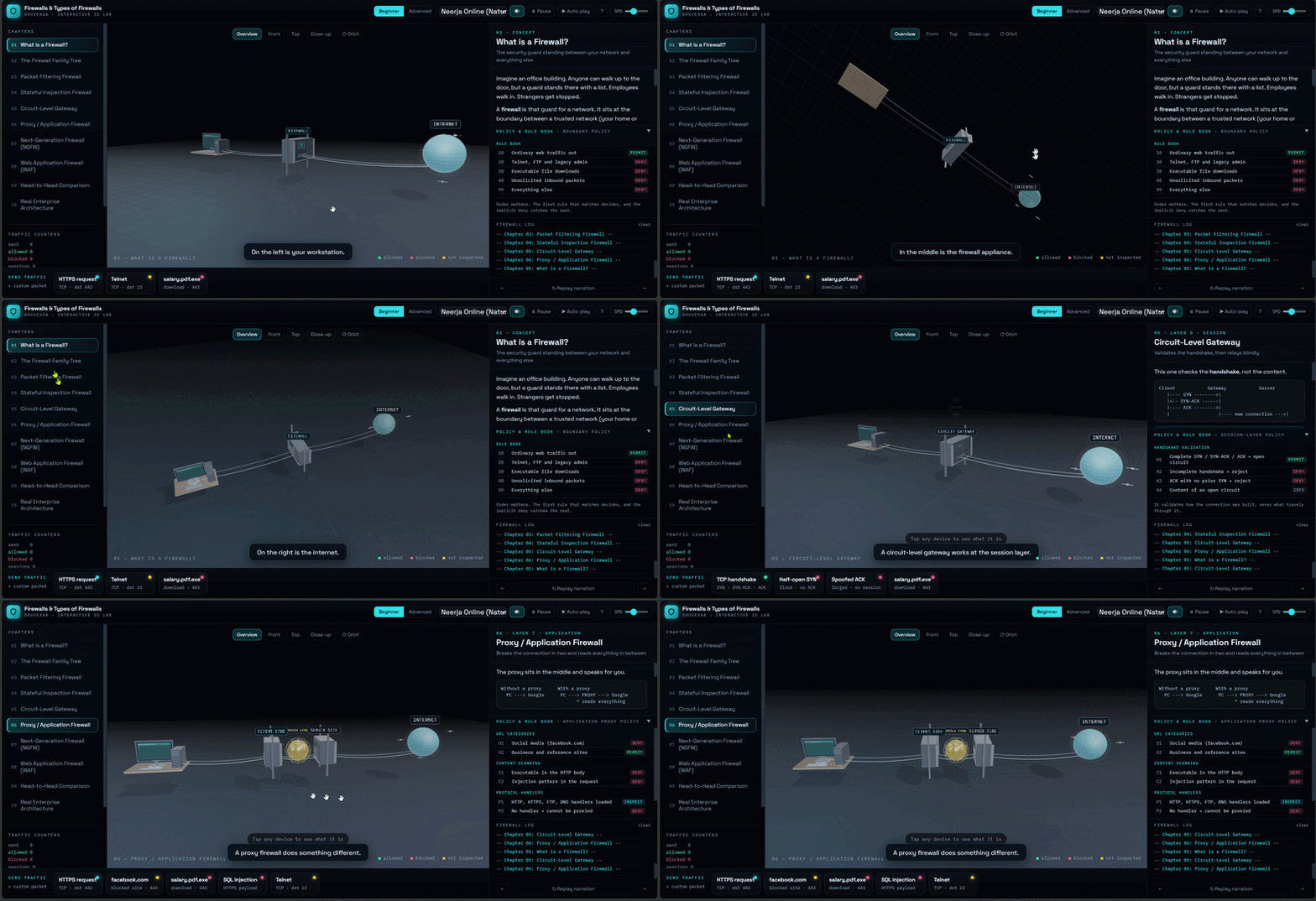
A firewall is a policy enforcement point placed at the boundary between a trusted network and an untrusted one. It checks every packet against an ordered rule set and decides to permit, deny, or drop it. But not every firewall inspects at the same depth — from stateless packet filters all the way up to Layer 7 proxies and Next-Generation Firewalls...
Explore & Experience Simulation
In the simulator, a packet walks up to the firewall and you watch exactly how deeply each generation of firewall looks before it makes a decision. On the left is your workstation, in the middle the firewall appliance, and on the right the internet. Send a packet and see whether it is permitted, denied, or dropped.
How a Firewall Works (Trust-Boundary Enforcement)
A firewall sits at the boundary between a trusted network (your home or office) and an untrusted one (the internet). Every generation answers the same single question — how deeply does the device look before it decides?
- Depth of inspection trades against throughput: the deeper a firewall reads, the more work it does per packet.
- The taxonomy maps onto the OSI model — that mapping is what separates one firewall type from the next.
The Firewall Family (mapped to OSI)
- 1. Packet Filtering (L3–L4): Stateless. Reads only the IP and transport headers and matches the five-tuple (src/dst IP, src/dst port, protocol). Fast and cheap, but blind above Layer 4.
- 2. Stateful Inspection (L3–L4): Keeps a connection table keyed on the five-tuple plus TCP state. The first packet runs the full rule set; later packets take a fast hash-lookup path. Return traffic is allowed automatically.
- 3. Circuit-Level Gateway (L5): Validates the TCP three-way handshake, then relays bytes blindly between two connections. SOCKS is the classic example; internal addressing stays hidden.
- 4. Proxy / Application Firewall (L7): Terminates the client connection and opens a fresh one to the origin. No packet forwarding — full Layer 7 visibility for URL filtering, MIME checks, and antivirus scanning.
- 5. Next-Generation Firewall (L2–L7): Single-pass parallel inspection. Application identity (allow Teams, block Discord) replaces the port as the policy object; TLS inspection is mandatory.
- 6. Web Application Firewall (L7): An HTTP specialist that guards one website — method, URI, headers, cookies, and body — using rule sets like the OWASP Core Rule Set.
Detailed Firewall Mechanics
1️⃣ Inspection Depth vs. Throughput
A packet filter only reads headers, so it is blazing fast. A proxy parses the whole application protocol, so it is an order of magnitude more expensive per session. Every step up the OSI stack buys visibility and costs speed.
⚠️ STATELESS WEAKNESS
A stateless filter keeps no connection table, so a crafted packet carrying an ACK flag looks identical to legitimate return traffic. That is the classic spoofing gap stateful inspection was built to close.
2️⃣ Stateful Memory & Its Cost
By tracking sequence numbers, a stateful firewall can drop out-of-window segments — but every tracked connection consumes memory, which makes the connection table itself a denial-of-service target (flood it with half-open sessions and it exhausts state).
3️⃣ Layer 7 & Virtual Patching
Because a proxy is an endpoint on both sides, it can normalise headers and scan payloads. A WAF adds virtual patching: it blocks exploitation of a known vulnerability at the edge while the app team ships a real fix — though an untuned WAF in blocking mode will break legitimate traffic.
🎯 Real Life Comparison
Think of a security guard at a building.
A packet filter only checks the envelope's address. A stateful firewall remembers who you are on the way back. A proxy opens the envelope and reads the letter. An NGFW does all of that in one glance — and a WAF is the specialist bodyguard hired for one VIP door.
Modern Use Cases (Defence in Depth)
No real network relies on a single firewall. Controls are layered so none is load-bearing:
- Scrubbing: absorbs volumetric floods upstream before they reach the stack.
- NGFW: enforces application and identity policy for the whole network.
- WAF: handles application-layer exploitation against published web services.
- Segmentation & zero trust: limit the blast radius after any one control fails.
Conclusion
Firewalls evolved by looking deeper and deeper into traffic — from headers, to connection state, to full application content. Understanding which control belongs at which point in the path is the real skill, and this simulation lets you see each one make its decision in 3D.
👑Top Pick


Visualizing Connectivity: The DHCP DORA Protocol in 3D
How does your laptop know which IP address to use when you join a café's Wi-Fi? It asks! This 3D simulation reveals the invisible conversation between your device and the router...
Demystifying Dynamic Host Configuration Protocol
Connecting to a network feels instant, but behind the scenes, a rapid four-step negotiation happens to assign your device a unique identity (IP Address). This project uses Three.js to visualize the DORA process, making the invisible data packets visible.
1. The "DORA" Sequence
The simulation breaks down the handshake into four animated stages:
- Discover (D): The client (laptop) shouts to the network, "Is there a DHCP server out there?"
- Offer (O): The Router receives the message and replies, "Yes, I have an IP address (192.168.1.5) available for you."
- Request (R): The client responds, "Great, I'll take that specific IP address, please."
- Acknowledge (A): The Router finalizes the deal, "It's yours! Here is your lease."
2. Visualizing the Invisible
Networking concepts are often abstract. This project makes them concrete by:
- Packet Travel: Using GSAP animations to show 3D data packets physically traveling across the "wire" between Client and Server meshes.
- State Changes: Visual feedback (color changes) on the router and client as packets are received and processed.
3. Interactive Learning
Unlike a static video, this simulation allows users to restart the process and includes Text-to-Speech (TTS) narration to audibly explain every step of the handshake as it happens on screen.
The Takeaway: By translating network protocols into 3D animations, we turn abstract handshake theories into a clear, observable mechanical process.

AI Myth-Buster: Separating Fact from Fiction
Is AI going to steal your job? Is it a conscious being? We break down the most common misconceptions about Artificial Intelligence using immersive 3D visualizations to separate sci-fi hype from reality...
Demystifying the Hype Around Artificial Intelligence
AI is seamlessly integrated into our daily lives, but rapid advancement brings a tidal wave of misunderstanding. To truly harness the power of AI, we need to understand what it actually is, and more importantly, what it isn't.
Busting the Top 5 Myths
- Myth: AI will steal everyone's job.
Reality: AI will change jobs, automating routine tasks and freeing humans for creative problem-solving. Think augmentation, not pure replacement. - Myth: AI is conscious and thinks like a human.
Reality: AI is sophisticated math and pattern recognition. Large Language Models predict text; they do not have feelings, beliefs, or a sense of self. - Myth: AI is completely objective and unbiased.
Reality: AI inherits human biases from its training data. Active human oversight is required to ensure fairness and equity. - Myth: AI is a magic bullet for any problem.
Reality: AI has limits, struggles with unlearned "edge cases," lacks common sense, and requires massive energy resources. - Myth: The "Terminator" scenario is imminent.
Reality: Immediate, practical risks like deepfakes, privacy violations, and copyright issues are far more pressing than a sci-fi robot uprising.
Interactive 3D Learning
This explainer uses Three.js and GSAP to visualize these concepts dynamically. Watch as abstract algorithmic concepts and neural networks are broken down into digestible, interactive 3D scenes.
The Takeaway: By prioritizing AI literacy and busting irrational fears, we can move past the hype and ensure this transformative technology serves to elevate humanity.
👑Top Pick


Networking
Default Gateway: The Door Out of Your Network
A Default Gateway is the router interface a device turns to whenever a packet's destination lies outside its own network. Every PC quietly compares source and destination networks using its subnet mask — matching networks go straight through the switch, while mismatched ones are handed off to this single "door" address...
Explore & Experience Simulation
In the context of the Simulator, the Gateway represents the single "door" between two IP networks — Network A (192.168.1.0/24) and Network B (10.0.0.0/24). Every packet that needs to leave its home network must pass through this router first.
How a Default Gateway Works (Layer 3 Routing)
Gateways operate at the Network Layer (Layer 3) of the OSI model, using IP addresses and subnet masks to make forwarding decisions.
- 1. Subnet Comparison: Every device applies its subnet mask to both the source and destination IP to check if they share the same network ID.
- 2. Same Network → Direct Delivery:
- If the network portions match, the switch delivers the frame directly.
- The router is never involved — it doesn't even see the packet.
- 3. Different Network → Gateway Hop: If the networks differ, the packet is sent to the configured gateway IP, which then routes it toward the destination.
Detailed Gateway Mechanics
1️⃣ The Three Essential Settings
Every device on a network stores three values: its own IP address, its subnet mask, and its default gateway address.
⚠️ MISSING GATEWAY ALERT
If the gateway field is empty or wrong, local file sharing still works fine — but any traffic destined outside the LAN (like websites) will fail with "Destination Unreachable."
2️⃣ One Address, Every Destination
A device doesn't need to know the route to every network on the internet. It only needs the gateway's address — the router handles everything beyond that door, hop by hop.
3️⃣ Two-Way Traffic
The gateway isn't just an exit — replies from outside networks also pass back through it on their way to the original device.
🎯 Real Life Comparison
Think of your neighborhood (the network).
The Default Gateway is the front gate. Talking to a neighbor? Just walk over directly. Mailing something out of town? You take it to the gate, and everything past that is out of your hands.
Modern Use Cases
Understanding the gateway is essential for:
- Network Troubleshooting: The first setting to check when "local works, internet doesn't."
- Router Configuration: Setting up home and enterprise networks correctly.
Conclusion
The Default Gateway is the quiet backbone of internet connectivity — a single address that lets any device reach any other network on Earth.

Networking
Network Types: PAN, LAN, MAN & WAN
Every computer network — from the Bluetooth bubble around your wrist to fibre stretched across the ocean floor — falls into one of four scales. PAN, LAN, MAN and WAN describe the same idea (devices talking to each other) at radically different distances, speeds, and costs...
Explore & Experience Simulation
In the context of the Simulator, you travel outward through four scales — a person, a building, a city, and finally the entire planet — watching the same idea (moving data from one device to another) played out at completely different distances and stakes.
The Four Scales — Where Data Goes
PAN
~10 metres
▶
LAN
~1 kilometre
▶
MAN
5–50 km
▶
WAN
Global
Each step outward multiplies the range by roughly 100× — and with it, latency, cost, and shared ownership all rise too.
Detailed Network Scales
1️⃣ PAN — Personal Area Network
The tiny bubble of connectivity around one person, roughly 10 metres. Your smartphone acts as the hub, pairing over Bluetooth or NFC with a smartwatch, wireless earbuds, and a laptop.
📡 KEY IDEA
Owned by one person, cheap, low power — but tiny range and modest speed (1–3 Mbps).
2️⃣ LAN — Local Area Network
A network inside one building or campus — an office, a school, or a home — owned by a single organisation. A central Layer-2 switch learns MAC addresses and forwards traffic only where it needs to go, while a Wi-Fi access point extends the same network wirelessly. Speeds run from 100 Mbps to 10 Gbps.
3️⃣ MAN — Metropolitan Area Network
Many LANs across one city, stitched together by an optical fibre ring buried under the roads — think bank branches syncing to headquarters. A ring topology gives every site two paths, so if a digger cuts the fibre on one side, traffic instantly wraps around the other way and self-heals in around 50 ms.
4️⃣ WAN — Wide Area Network
Networks of networks spanning countries and continents — the Internet is the largest WAN ever built. About 99% of intercontinental traffic rides submarine fibre cables along the ocean floor, with satellites covering the rest. Distance now costs real time: light itself needs roughly 100+ milliseconds to make a round trip across the planet.
🎯 Real Life Comparison
Think of it as zooming a camera outward.
PAN is your pocket — everything within arm's reach.
LAN is your building — everyone under one roof, on one network.
MAN is your city — many buildings sharing one metro backbone.
WAN is the whole world — countless networks, owned by no one, handing traffic to each other across oceans.
Side-by-Side Comparison
- PAN: ≈10 m · 1–3 Mbps (Bluetooth) · owned by one person · earbuds, smartwatch, phone hotspot.
- LAN: ≈100 m–1 km · 100 Mbps–10 Gbps · owned by one organisation · office, home, school lab.
- MAN: 5–50 km · 10 Mbps–10 Gbps · owned by an ISP/city · bank branches, cable TV, city Wi-Fi.
- WAN: country → global · 100+ Gbps backbone, higher latency · leased across many providers · the Internet itself.
The Pattern to Remember
As networks grow larger, speed-per-rupee falls, latency rises, and ownership fragments across more parties. A PAN is private and near-instant; a WAN is shared infrastructure limited by the physics of distance. Memory hook: Pocket → Local building → Metro city → World.
Conclusion
PAN, LAN, MAN and WAN aren't different technologies so much as the same networking problem solved at four completely different distances — and understanding where each one's boundary lies is the first step to understanding how the whole Internet fits together.
👑Top Pick


Networking
TCP: The Transport Layer Deep Dive
Transmission Control Protocol (TCP) is a Layer 4 protocol that transforms IP's unreliable, "lazy postman" delivery into a reliable, ordered, error-checked byte stream. Every byte is numbered, every segment is acknowledged, and every connection begins with a careful three-way handshake before a single byte of real data ever moves...
Explore & Experience Simulation
In the context of the Simulator, TCP is explored across 11 full chapters — from encapsulation and header anatomy, to the 3-way handshake, sequence & acknowledgment numbers, error checking, flow control, congestion control, and the complete end-to-end journey of opening a website.
TCP's 5 Core Promises (Layer 4 Reliability)
TCP sits above the unreliable Network Layer and guarantees five things IP alone cannot.
- 1. Reliable Delivery: Lost data is detected via timers and duplicate ACKs, then automatically resent.
- 2. Ordered Delivery:
- Every byte carries a Sequence Number.
- The receiver reassembles data in the exact original order, even if segments arrive scrambled.
- 3. Error Checking: A 16-bit checksum fingerprints every segment; corrupted data is silently discarded and retransmitted.
Detailed TCP Mechanics
1️⃣ The 3-Way Handshake
Before any data flows, both sides exchange starting sequence numbers.
🔄 SYN → SYN-ACK → ACK
Client sends SYN (Seq=100). Server replies SYN-ACK (Seq=500, Ack=101). Client confirms with ACK=501. Connection is now ESTABLISHED.
2️⃣ Flow Control (Protecting the Receiver)
The receiver advertises a Window Size showing free buffer space. If the window drops to 0, the sender pauses completely — sending only tiny probes — until the receiver's app catches up and reopens the window.
3️⃣ Congestion Control (Protecting the Network)
TCP grows its congestion window exponentially during Slow Start, then linearly during Congestion Avoidance — and halves it sharply on packet loss, producing the famous "sawtooth" graph shared by every TCP flow on the internet.
🎯 Real Life Comparison
Think of a stream of numbered postcards (the network).
TCP is the diligent courier who numbers every card, waits for a receipt (ACK) on each batch, resends any postcard that never gets confirmed, and slows down if the mailbox (buffer) or the road (network) gets too full.
Modern Use Cases
TCP underlies nearly all reliable internet communication:
- Web Browsing: HTTPS (port 443) runs over TCP for guaranteed page delivery.
- File Transfer & Email: FTP, SMTP, and IMAP all rely on TCP's reliability guarantees.
Conclusion
TCP is the quiet workhorse behind almost every reliable connection on the internet — turning an unpredictable network into a dependable, ordered stream of data, one carefully numbered byte at a time.

How Your Computer Connects to the World: A Guide to DNS, NAT, and PAT
Ever wonder what happens in the split second between typing google.com and the page loading? It’s a complex relay race involving three major technologies...
This guide breaks down these concepts into simple terms, following the journey of a single request from your laptop to a web server.
1. DNS (Domain Name System)
The Phonebook of the Internet
Computers only understand numbers called IP Addresses. DNS acts as the translator. When you type a URL, your computer asks a DNS Server for the IP, allowing it to find the exact destination.
2. NAT (Network Address Translation)
The Front Desk Clerk
Since ISPs usually provide only one public IP, NAT allows your router to act as a middleman. It swaps your device's "Private IP" for a "Public IP" to communicate with the world while keeping your internal network secure.
3. PAT (Port Address Translation)
The Apartment Numbers
PAT ensures data goes to the right device. By assigning unique Port Numbers (e.g., :1025 for a laptop, :1026 for a phone), the router knows exactly which screen requested the specific information when it returns.
The Complete Flow:
- DNS Lookup: example.com becomes 93.184.216.34.
- NAT/PAT: Router swaps Private IP for Public IP + Port :1025.
- Response: Server sends data back to Port :1025.
- Delivery: Router forwards data to the correct local device.
The Takeaway: These three technologies allow billions of devices to stay connected, secure, and organized on a global scale.
👑Top Pick

How Devices Find Each Other on a LAN: A Guide to ARP, Ethernet Frames, and Broadcasts
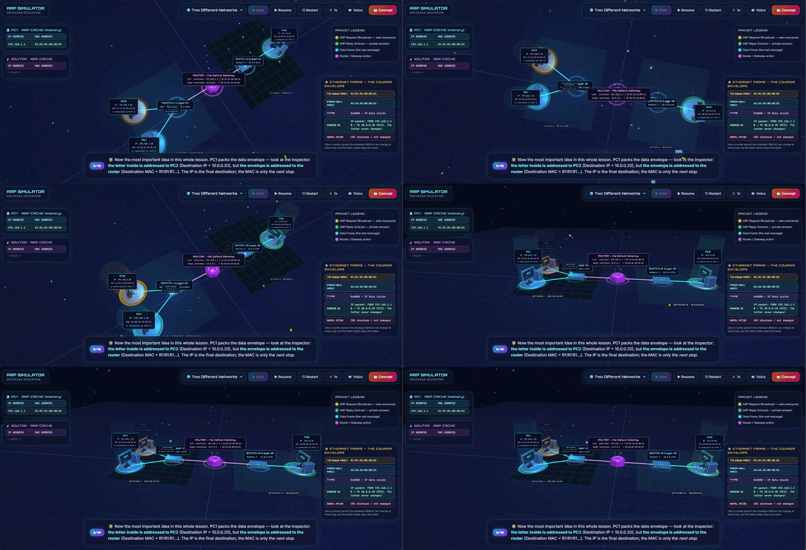
You know a device's IP address, but on a local network, data doesn't travel by IP alone — it travels inside Ethernet frames addressed to physical MAC addresses. So how does your computer learn the MAC address behind an IP? That's where ARP comes in...
This guide walks through how ARP (Address Resolution Protocol) resolves IP addresses to MAC addresses, how that request is wrapped inside an Ethernet frame, and why a broadcast is necessary to make it all work.
1. Why ARP Exists
The Missing Link Between Layer 3 and Layer 2
IP addresses (Layer 3) get data to the right network and device logically, but Ethernet switches only understand MAC addresses (Layer 2) to actually deliver a frame on the wire. Before a device can send a packet to another device on the same LAN, it must know that device's MAC address. ARP is the protocol that maps a known IP address to its corresponding unknown MAC address.
2. The ARP Request (Broadcast)
Shouting Into the Room
When a device needs a MAC address it doesn't have cached, it creates an ARP Request and sends it as a broadcast — destination MAC FF:FF:FF:FF:FF:FF. Every device on the local network segment receives and processes this frame, essentially asking aloud: "Who has IP 192.168.1.10? Tell 192.168.1.5." Only the device that owns that IP address will respond; everyone else silently discards the request after checking it doesn't match their own IP.
3. The ARP Reply (Unicast)
A Direct, Private Answer
The device that owns the requested IP address replies directly to the requester using a unicast frame (not a broadcast), since it now knows exactly who asked and their MAC address from the request frame. The reply says: "I am 192.168.1.10, and my MAC address is AA:BB:CC:DD:EE:FF." The original requester stores this mapping in its local ARP cache/table so it doesn't need to broadcast again for a while.
4. Inside the Ethernet Frame Carrying ARP
The Envelope and the Letter
ARP messages are not carried inside IP packets — they ride directly inside an Ethernet frame, using EtherType 0x0806 to signal "this is ARP, not IP." A typical Ethernet frame carrying an ARP request looks like this:
- Destination MAC: FF:FF:FF:FF:FF:FF (broadcast, for a request)
- Source MAC: the sender's own physical address
- EtherType: 0x0806 (identifies the payload as ARP)
- ARP Payload: Hardware type, Protocol type, Hardware/Protocol address lengths, Opcode (1 = Request, 2 = Reply), Sender MAC, Sender IP, Target MAC (all zeros in a request), Target IP
- Frame Check Sequence (FCS): used for error detection
5. Why Broadcast Is Necessary (and Its Limits)
The Cost of Asking Everyone
Broadcasting is required because, before the reply arrives, the sender has no idea which device on the LAN owns the target IP — there's no way to unicast a request to an unknown MAC. However, broadcasts are also why ARP stays confined to a single broadcast domain: routers do not forward broadcast frames between networks, so ARP only resolves addresses for devices on the same local segment. This is also why large flat networks with too many hosts can suffer from "broadcast storms" if ARP traffic isn't managed with VLANs or other segmentation.
The Complete Flow:
- Trigger: Device A wants to send data to IP 192.168.1.10 but lacks its MAC address.
- ARP Request: Device A broadcasts an Ethernet frame (dest MAC FF:FF:FF:FF:FF:FF, EtherType 0x0806) asking "Who has 192.168.1.10?"
- Filtering: All devices on the LAN receive the frame; only the device with matching IP processes it further.
- ARP Reply: Device B unicasts back its MAC address directly to Device A.
- Caching: Device A stores the IP–MAC mapping in its ARP table for future use.
- Delivery: Device A can now address Ethernet frames directly to Device B's MAC.
The Takeaway: ARP bridges the gap between logical IP addressing and physical MAC addressing by broadcasting a question to the whole local network and letting the right device answer privately — all wrapped inside a standard Ethernet frame.

How Your OS Manages Memory: A Guide to Allocation Algorithms & Fragmentation
Ever wonder how your computer decides where to put a newly opened app in its RAM? It’s a continuous game of Tetris, placing processes into memory blocks using specific allocation algorithms...
This guide breaks down how the Operating System assigns memory to your programs and the "fragmentation" issues it leaves behind in the process.
1. First Fit
The Speedy Seat-Finder
The OS scans the memory from the beginning and allocates the very first available block that is large enough. It's incredibly fast but can leave useless, tiny gaps near the start of the memory over time.
2. Best Fit
The Perfectionist
The OS searches the entire memory for the smallest available block that is big enough to hold the process. It saves large blocks for later, but creates tiny, unusable leftover spaces called "splinters."
3. Worst Fit
The Space Maximizer
The OS intentionally places the process in the absolute largest available memory block. The idea is that the leftover space will be big enough to still be useful for another process later on.
4. The Problem: Fragmentation
The Wasted Space
Internal Fragmentation happens when a block is slightly larger than the process, wasting space locked inside the allocated block. External Fragmentation occurs when the total free memory is enough for a new process, but it's scattered in small, unusable pieces across the RAM.
The Complete Flow:
- Request: A new program asks the OS for a specific amount of memory.
- Algorithm Search: The OS uses First, Best, or Worst Fit to find a suitable gap in RAM.
- Allocation: The process is loaded into the chosen block.
- Fragmentation: Leftover space from the allocation becomes either internal waste or scattered external gaps.
The Takeaway: These algorithms dictate how efficiently your computer uses its RAM, constantly balancing execution speed against long-term memory optimization.

3D USB Pen Drive with user interaction
A 3D visualization comparing Old Generations to new Generations USB 2.0, 3.0, and 4.0 data transfer speeds with Calculation.
Title: The Evolution of Speed: A Deep Dive into USB 2.0, 3.0, and 4.0 Data Transfer
The Universal Serial Bus, or USB, has become one of the most ubiquitous and indispensable technologies in modern computing. From its humble beginnings, it has evolved into a high-speed interface that we rely on for everything from transferring files and charging devices to connecting peripherals. The pen drive, a portable storage device that utilizes this interface, has become a symbol of data mobility. However, not all USBs are created equal. The standards that govern them—USB 2.0, 3.0, and the latest USB 4.0—represent significant leaps in data transfer technology. Understanding the differences between these generations is key to appreciating how much faster and more efficient our digital lives have become.
Our interactive 3D simulation brings this evolution to life, visualizing the stark contrast in data transfer speeds between these three generations. By watching digital packets of information flow from a device to a pen drive, users can intuitively grasp the magnitude of improvement with each new standard. But what is happening behind the scenes?
USB 2.0: The High-Speed Era Begins
Introduced in the year 2000, USB 2.0, also known as "Hi-Speed USB," was a revolutionary step up from its predecessor, USB 1.1. It boasted a theoretical maximum transfer speed of 480 megabits per second (Mbps), which translates to about 60 megabytes per second (MB/s). In the real world, due to protocol overhead and other factors, users typically experienced speeds closer to 35 MB/s. At the time, this was incredibly fast and perfectly adequate for transferring documents, music files, and standard-resolution photos.
One of the key limitations of USB 2.0 was its half-duplex operation. This means that data could only be sent in one direction at a time—either to the device or from the device. Imagine a single-lane road where traffic has to stop to let cars from the opposite direction pass. This one-way communication created a bottleneck, especially when dealing with larger files or simultaneous read/write operations. The simulation clearly depicts this, showing a slower, more deliberate transfer of data packets. The physical connector for USB 2.0 typically had four pins: two for power and two for data.
USB 3.0: The SuperSpeed Revolution
The game changed in 2008 with the arrival of USB 3.0, marketed as "SuperSpeed USB." This new standard introduced a massive increase in theoretical speed, jumping to 5 gigabits per second (Gbps), which is more than ten times faster than USB 2.0. This equates to a theoretical maximum of 625 MB/s, with real-world speeds often reaching around 400-500 MB/s. This leap made transferring high-definition movies, large software installations, and entire photo albums a matter of seconds rather than minutes.
The primary innovation behind this speed boost was the introduction of full-duplex communication. USB 3.0 added five extra pins to its connector, for a total of nine. These extra pins allowed for simultaneous two-way data transfer. Going back to our road analogy, this is like upgrading from a single-lane road to a multi-lane highway where traffic can flow in both directions at the same time without interruption. Our 3D visualization showcases this beautifully, with data packets moving swiftly and concurrently, dramatically reducing transfer times. To easily distinguish them, USB 3.0 ports and connectors are often colored blue. Later revisions, like USB 3.1 and 3.2, further increased these speeds, pushing the boundaries to 10 Gbps and 20 Gbps respectively, but they all fall under the "SuperSpeed" family.
USB 4.0: The Future of Connectivity is Here
The latest standard, USB 4.0, released in 2019, represents another monumental leap. Built upon the foundation of the Thunderbolt 3 protocol, which was developed by Intel, USB 4.0 doubles the maximum speed of the fastest USB 3.2 standard, reaching a blistering 40 Gbps (approximately 5,000 MB/s). This incredible bandwidth opens up possibilities that were previously unimaginable for a standard USB port. With USB 4.0, a user can transfer a full-length 4K movie in just a few seconds.
But USB 4.0 is about more than just raw speed. It introduces intelligent bandwidth management. The protocol can dynamically allocate resources based on the needs of the connected devices. For example, if you connect an external 8K monitor and a high-speed storage drive to the same USB 4.0 port, the system will intelligently manage the 40 Gbps of bandwidth, ensuring the display gets the steady stream of data it needs to run smoothly while the storage drive uses the remaining capacity for fast file transfers. This efficient sharing of bandwidth was not possible with older standards.
Furthermore, USB 4.0 is exclusively built on the USB-C connector type, a reversible, more robust connector that can handle higher power delivery for charging laptops and other large devices. While previous USB generations also adopted the USB-C form factor, it is mandatory for USB 4.0, simplifying the physical connection landscape. Our simulation visualizes this ultimate speed, showing a torrent of data flowing almost instantaneously, illustrating why USB 4.0 is the new benchmark for high-performance connectivity.
By interacting with this 3D simulation, users don't just read about these differences; they see them in action. They can experience firsthand why upgrading to a newer USB standard can drastically improve their workflow and save valuable time in an increasingly data-driven world.

3D Simulation Mobile Call Flow The Invisible Path of a Mobile Call with user interaction
Interactive 3D Simulation: Why Your Phone Rings Instantly When Someone Calls even if no app is open and the processor seems idle.
Interactive 3D Simulation: Why Your Phone Rings Instantly When Someone Calls even if no app is open and the processor seems idle. Discover how mobile telephony works through the hidden story of the Modem, Kernel, and Telephony magic.The Unseen Journey: How a Mobile Call Connects Instantly
In a world of constant connectivity, the mobile phone call remains one of the most fundamental and reliable forms of communication. We press a button, and within seconds, we hear a ring on the other side of the planet. This near-instantaneous connection feels like magic, especially when we consider that our phone might have been sitting idle in our pocket just moments before. No app was open, the screen was off, and yet, it sprang to life to connect a call. How is this possible? The answer lies in a complex, yet incredibly efficient, chain of events that takes place deep within the phone's hardware and the global cellular network.
Our interactive 3D simulation demystifies this process, revealing the hidden path a mobile call takes from the moment you dial to the instant the other phone rings. It’s a journey that involves specialized hardware, low-level software, and a sophisticated network infrastructure working in perfect harmony. The secret lies in the fact that your phone is never truly "idle."
The Always-On Gatekeeper: The Modem and Baseband Processor
The hero of this story is a tiny, highly specialized component inside your smartphone: the cellular modem, also known as the baseband processor. This is a completely separate computer within your main computer (the smartphone). While the main application processor (CPU)—the one that runs your apps, games, and user interface—can go into a low-power sleep state to conserve battery, the modem is always on, albeit in a very low-power listening mode.
The modem's single, critical job is to maintain a constant, passive connection with the nearest cell tower. It periodically "wakes up" for a few milliseconds to listen for a paging signal from the network. A paging signal is a broadcast message sent out by cell towers in a specific area, essentially calling out for a particular phone. Think of it as a town crier calling your name in a crowded square; even if you're not actively doing anything, your ears are always open to hear your name. This process is incredibly energy-efficient, using only a tiny fraction of the phone's battery power. Our simulation visualizes this modem as a vigilant guardian, always connected to the cellular network's invisible web.
The Call Begins: The Paging Channel
When someone dials your number, their network sends a request to your network to find your phone. Your network's Mobile Switching Center (MSC), the brain of the cellular system, knows the last known location of your phone (which group of cell towers it was near). The MSC then instructs those cell towers to send out a paging signal on a special radio channel called the Paging Channel.
This signal contains your phone's unique identifier. The ever-listening modem on your device detects this signal and immediately recognizes its own "name." This is the trigger that starts the chain reaction. The modem instantly wakes up from its low-power state into a fully active mode.
Waking the Giant: The Kernel and the Application Processor
Once the modem confirms the incoming call, it needs to wake up the main brain of the phone—the application processor (CPU) and the operating system (OS). It does this by sending a hardware interrupt. An interrupt is a high-priority signal that tells the CPU to immediately stop what it's doing (or wake up from sleep) and pay attention to a critical task.
The operating system's kernel, the core component that manages all hardware, receives this interrupt. The kernel is the bridge between the phone's hardware (like the modem) and its software (the apps and user interface). It processes the signal from the modem and understands that an incoming call needs to be handled.
The kernel then wakes up the entire system. It launches the necessary telephony services—the software responsible for managing calls. This includes the phone app's user interface, which is what you see on the screen. The kernel instructs the audio hardware to activate the speaker and prepare to play the ringtone. It also tells the vibration motor to start, if that setting is enabled. This all happens in a fraction of a second.
Establishing the Connection: The Final Handshake
Simultaneously, while the main processor is waking up and preparing the user interface, the modem is busy communicating with the cell tower to formally establish the call. It sends a confirmation signal back to the network, acknowledging the page. The network then assigns a dedicated voice channel—a specific set of radio frequencies—for your call. The modem tunes itself to these frequencies, and a secure, dedicated connection is established between your phone and the cell tower.
Once this channel is locked in, the network signals the caller's phone that you are ready, and they hear the ringing tone. On your end, your phone is already ringing and vibrating, displaying the incoming call on the screen. The entire process, from the initial page to the first ring, is typically completed in under two seconds.
Our 3D simulation allows you to witness this incredible sequence step-by-step. You can see the paging signal travel from the tower, watch the modem wake up the kernel and CPU, and observe how the dedicated voice channel is established. It transforms an abstract concept into a tangible, understandable process, revealing the beautiful engineering that makes instant communication possible.

Networking
Network Switches: The Intelligent Hub of Connectivity
A Network Switch is a fundamental piece of networking hardware that connects devices on a computer network. Unlike a basic hub, which blindly broadcasts data to every device, a switch is "intelligent." It uses packet switching to receive, process, and forward data...
In the context of the 3D Simulator you are using, the switch acts as the central traffic director. When you select a "Source" and a "Destination" in the simulator and click "Send Packet," you are visualizing the switch's core job: taking a data frame from one port and accurately delivering it to another.
How a Network Switch Works (The "Matter")
Switches operate primarily at Layer 2 (Data Link Layer) of the OSI model. Their efficiency comes from their ability to "learn" the network topology.
- 1. MAC Addressing: Every network interface card (NIC) has a unique identifier called a Media Access Control (MAC) address. In the Simulator, each device (e.g., PC A, Printer B) has a simulated MAC address.
- 2. The CAM Table (Content Addressable Memory): The "brain" of the switch.
- Learning: When data enters a port, the switch records the Source MAC and Port Number.
- Forwarding: Known destinations get Unicast (direct) traffic.
- Flooding: Unknown destinations cause the data to be sent to all ports (except origin) until the device replies.
- 3. Collision Domains: Unlike a Hub where only one device talks at a time, a Switch makes every port its own collision domain. PC A can talk to PC B while PC C talks to PC D simultaneously.
Detailed Switch Operation Breakdown
1️⃣ Switch Has a MAC Address Table (CAM Table)
The switch maintains a table mapping MAC addresses to ports:
| Device MAC Address | Port Number |
|---|---|
| AA:BB:CC:DD:EE:01 | Port 1 |
| AA:BB:CC:DD:EE:02 | Port 3 |
This table is created automatically as traffic passes.
2️⃣ Learning Phase (MAC Learning)
Whenever the switch receives a frame, it checks the source MAC and maps it to the incoming port. If the MAC is new, it adds it; otherwise, it refreshes the timer.
3️⃣ Forwarding Phase (Decision Making)
- 🚀 A. Unicast Forwarding: If destination MAC is known, send only to that port.
- 🚀 B. Flooding: If destination MAC is unknown, flood to all ports.
- 🚀 C. Filtering: If source and destination are on the same port, drop the frame.
4️⃣ 🔁 Aging MAC Table
Entries are removed after 5 minutes (default) if no traffic is seen, avoiding stale entries.
5️⃣ 📦 Switch Avoids Collisions
Communication is full duplex (send + receive same time). No collisions occur.
6️⃣ 🧠 Internal Working
Uses ASICs for wire-speed decisions. Methods include Store-and-Forward (checks errors) and Cut-Through (fastest).
🎯 Real Life Example: How a Frame Moves
- ARP Request: PC1 needs PC3. Broadcasts. Switch floods.
- ARP Reply: PC3 replies. Switch learns PC3 is on Port 3.
- Data Transfer: Switch now sends data ONLY to Port 3 (Unicast).
Use Cases
- Small Office (SOHO): File sharing and printer access.
- Enterprise LANs: Using VLANs to separate Finance traffic from Guest Wi-Fi.
- Data Centers: High-performance Top-of-Rack switches handling 10Gbps+ traffic.
- IP Camera Surveillance (PoE): Powering cameras directly through the ethernet cable.
Conclusion
The network switch is the unsung hero of the modern internet. While routers get the credit for connecting us to the World Wide Web, switches do the heavy lifting of moving data around our local environments efficiently.

Visualizing the Invisible: A 3D Dive into TCP vs. UDP in Computer Networks
Visualizing the Internet's 'Rules of the Road': A Guide to the 3D Network Simulator. Every time you browse a website, download a file, or stream a live match...
Visualizing the Internet's 'Rules of the Road': A Guide to the 3D Network Simulator
Every time you browse a website, download a file, or stream a live match, your computer is following a set of rules, or "protocols," to send and receive data. The 3D Network Simulator is a powerful interactive tool designed to pull back the curtain on this invisible process. It brings to life the two most important of these rules—TCP and UDP—to show you why the internet works the way it does.
The simulation is split into two key scenarios, each demonstrating a different side of the internet's core trade-off: Reliability vs. Speed.
1. The TCP Scenario: The Reliable Workhorse
TCP (Transmission Control Protocol) is the internet's "reliable" protocol. Think of it like a registered phone call where you must establish a connection and confirm the other person is ready before you start talking. It's used for tasks where every single piece of data is critical.
This scenario masterfully visualizes TCP's two defining features:
The 3-Way Handshake:
When you start a TCP action (like searching "Google"), the simulation doesn't just send your data. It first shows the "phone call" being established.
- [SYN]: Your computer sends a "Synchronize" packet, asking the server, "Are you there?"
- [SYN-ACK]: The server replies with a "Synchronize-Acknowledge" packet, saying, "Yes, I'm here and ready!"
- [ACK]: Your computer sends a final "Acknowledge" packet: "Great, I'm starting to talk."
Only after this handshake is complete does the data (your search request) begin to flow.
Reliable, Ordered Delivery:
In the file download simulation, you see a constant, two-way conversation. For every [Data] packet the server sends, your computer sends back an [ACK] packet. This is a visual representation of acknowledgment. It's TCP's guarantee that every single packet is received in the correct order, ensuring your file isn't corrupted.
The takeaway: TCP is used for websites, emails, and downloads because it prizes accuracy above all else. It's slower to start, but it's 100% reliable.
2. The UDP Scenario: The Need for Speed
UDP (User Datagram Protocol) is the "fast" protocol. Think of it like sending a stream of postcards—you just write them and send them off as fast as you can. You don't wait for a reply, and you don't know if they all arrive. It's used for real-time applications where speed is more important than perfect accuracy.
This scenario highlights UDP's advantages and its very real trade-offs:
No Handshake:
When you start the "live stream," the server immediately begins firing [UDP Data] packets. There is no 3-way handshake, making the connection feel instantaneous.
Bandwidth, Buffering & Packet Loss:
This is the simulation's most brilliant feature. The user can control the "network bandwidth" with a slider to see real-world problems happen live:
- High Bandwidth: The stream is smooth, with packets (and cricket plays) arriving in a fast, steady flow.
- Low Bandwidth: The simulation triggers two problems:
- Buffering: The packets arrive too slowly. The 2D cricket game is forced to pause and display a "Buffering..." overlay because the data for the next play simply hasn't arrived yet.
- Packet Loss: Some 3D packets are "lost" (they fade away). This isn't just a visual effect; it has real consequences.
The Live Cricket Match:
This is the key. The 2D cartoon is not a video. Its animation is directly powered by the 3D packets. When a packet for a "Six" arrives, the "Six" animation plays and the score updates. If that packet is lost due to low bandwidth, the play never happens. The user sees the game freeze and buffer, creating an unbreakable link between the 3D packet flow and the final user experience.
Conclusion: From Abstract to Obvious
This simulation's power lies in its ability to translate invisible, complex network processes into a tangible, interactive story.
By contrasting the methodical, handshake-first TCP download with the fast, and sometimes chaotic, UDP stream, any user can instantly grasp the fundamental trade-off at the heart of the internet. It visually proves why your stream buffers and what "packet loss" actually means, turning abstract technical terms into a clear, cause-and-effect experience.
👑Top Pick


Scenario 1:-Journey of Data Through a VPN – 3D Simulation with user interaction
A 3D journey showing how your data travels securely through VPN servers to unlock privacy, safety, and access worldwide.
Unlocking the Digital World Safely: A Comprehensive Guide to How VPNs Work
Introduction: Your Private Tunnel on the Information Superhighway
In today's interconnected world, nearly every aspect of our lives touches the internet. We shop, bank, learn, and connect with others online. But as we send our personal data across this vast network, how can we be sure it's safe from prying eyes? The answer for millions of people is a Virtual Private Network, or VPN.
A VPN is more than just a technical tool; it's your personal, encrypted tunnel through the public internet. It shields your online activities from your Internet Service Provider (ISP), hackers on public Wi-Fi, and even advertisers trying to track your every move. This guide will demystify the technology behind VPNs. We'll break down exactly how they work, step by step, exploring the core concepts of encryption, tunneling, and IP masking that make them such an essential tool for digital privacy and security.
What is a VPN, Really? The Core Concepts Explained
At its heart, a VPN serves three primary functions:
Privacy: It prevents your ISP and others on your local network from seeing what you do online. Because all your traffic is encrypted, they only see that you're connected to a VPN server, not the websites you visit or the data you exchange.
Security: It creates a secure, encrypted connection, which is especially crucial on unsecured networks like public Wi-Fi. This encryption acts like a sealed, armored envelope for your data, making it unreadable to anyone who might intercept it.
Anonymity & Access: It masks your real IP address (your device's public address on the internet) and replaces it with the IP address of the VPN server you connect to. This makes it appear as if you are browsing from the server's location, allowing you to bypass geographic restrictions and enhance your anonymity.
To achieve this, a VPN uses a combination of powerful technologies, which we can explore in a step-by-step journey of a single data packet.
The Journey of Data: How a VPN Works from Start to Finish
Imagine you are in India and want to watch a video on YouTube. Here’s the detailed process of how a VPN handles your request when you connect through a server in the United States.
Step 1: The Handshake – Establishing a Secret Language
Before any data is sent, your device (the VPN client) and the VPN server need to establish a secure connection. This is done through a process called a cryptographic handshake.
Authentication: Your device proves to the server that you are a legitimate user (using your username/password or a certificate).
Key Exchange: The client and server securely exchange cryptographic keys. They use these keys to create a unique set of session keys—temporary keys that will be used to encrypt and decrypt all the data sent during this specific connection. This ensures that even if one session were somehow compromised, future sessions would remain secure with new keys.
This handshake establishes a trusted and completely private channel for communication, like two spies agreeing on a secret code before they start talking.
Step 2: Encapsulation & Tunneling – Creating the Virtual Cable
Once the secure channel is established, the VPN client on your device creates a virtual network adapter. Think of this as a new, software-based network port. Your operating system is then configured to route your internet traffic through this virtual adapter instead of your physical one.
This process creates the "tunnel." When you send a request to YouTube, the following happens:
Original Packet: Your device creates a data packet destined for YouTube, containing your request and your real (Indian) IP address.
Encryption: Before it leaves your device, the VPN client encrypts this entire packet using the agreed-upon session key. The packet is now scrambled and unreadable to anyone without the key.
Encapsulation: The VPN client then "encapsulates" this encrypted packet by placing it inside a new, outer packet. This outer packet's destination is not YouTube, but the VPN server in the US.
This is like writing a letter, putting it in a security envelope (encryption), and then putting that envelope inside a larger courier package addressed to your trusted middleman—the VPN server (encapsulation).
Step 3: The Relay – The VPN Server at Work
Your encapsulated packet travels across the public internet to the VPN server in the US. Your ISP can see this packet, but because its contents are encrypted, it has no idea what you're doing. It only knows that you sent some data to an IP address in the US.
When the VPN server receives the packet, it:
Removes the Outer Layer: It strips away the outer packet.
Decrypts the Contents: It uses the shared session key to decrypt the inner packet, revealing your original request for YouTube.
Forwards the Request: The server then sends your request to YouTube, but with a crucial change: it uses its own US-based IP address as the source.
To YouTube, the request appears to have come directly from the server in the United States, not from your device in India. Your real IP address is completely hidden.
Step 4: The Return Journey – Securely Back to You
YouTube processes the request and sends the video data back—not to you, but to the source of the request: the VPN server in the US. The server then encrypts this data, puts it in a new packet addressed to your device, and sends it back through the secure tunnel.
Finally, the VPN client on your device receives the packet, decrypts it, and passes the video data to your browser. This entire round-trip process happens in milliseconds, allowing you to browse and stream seamlessly and securely.
Key VPN Features and Terminology
To fully grasp how VPNs function, it's helpful to understand a few key terms:
Encryption Standards (like AES-256): This is the algorithm used to scramble your data. AES-256 is considered the gold standard, used by governments and security institutions worldwide. It has a key size of 256 bits, meaning there are 2^256 possible combinations—a number so large that it would take the world's most powerful supercomputers billions of years to crack.
VPN Protocols (WireGuard, OpenVPN, IKEv2): These are the sets of rules that govern how the VPN tunnel is built and maintained.
WireGuard®: A modern, fast, and lean protocol known for its excellent performance and state-of-the-art cryptography.
OpenVPN: The industry workhorse, highly secure and configurable, though sometimes slightly slower than WireGuard.
IKEv2/IPsec: Very stable and reliable, especially for mobile users, as it can quickly re-establish a connection if you switch between Wi-Fi and cellular data.
Kill Switch: A critical security feature. If your VPN connection unexpectedly drops, the kill switch immediately blocks all internet traffic from your device. This prevents any unencrypted data or your real IP address from accidentally leaking out.
No-Logs Policy: A promise from a VPN provider that they do not store or monitor any records of your online activity, such as the websites you visit or the files you download. For true privacy, it is essential to choose a provider with a strict, independently audited no-logs policy.
Split Tunneling: A feature that lets you choose which apps or websites use the VPN and which connect directly to the internet. For example, you could route your browser traffic through the VPN for privacy while allowing a gaming app to connect directly for lower latency.
Conclusion: An Essential Tool for the Modern Internet User
A Virtual Private Network is a powerful and versatile technology that puts you back in control of your digital life. By creating an encrypted tunnel, masking your IP address, and routing your traffic through a secure server, a VPN provides a vital layer of security and privacy against a wide range of online threats.
Whether you're protecting your data on public Wi-Fi, securing your digital footprint from trackers, or simply accessing content freely and safely, understanding how a VPN works reveals its immense value. It transforms the chaotic public internet into a private, secure, and more open environment, making it an indispensable tool for anyone who values their online freedom and safety.

Scenario 2:-Journey of Data Through a VPN – 3D Simulation with user interaction
Follow the 3D path of your data as it is encrypted and routed through secure VPN servers, providing enhanced privacy, data protection, and unrestricted global access.
A Guide to Your Digital Journey: Understanding Your Connection
Introduction: Visualizing Your Path Across the Internet
Welcome! This page features two powerful simulations designed to demystify how your data travels across the internet. Each visualization tells a part of the story.
The Conceptual Animation (bottom-right): This provides a simplified, foundational look at the core difference between a standard, unprotected internet connection and a basic, secure VPN connection. It’s the perfect place to start.
The Interactive Globe (main view): This demonstrates a more detailed, real-world scenario. You can see how data packets travel across the globe, how your virtual location changes, and how a VPN reroutes your traffic through a server in another country.
By understanding both, you'll gain a true appreciation for the layers of technology that protect you and your data online. Let's begin with the fundamentals.
Part 1: The Core Concept (The Conceptual Animation)
The animation in the corner of your screen illustrates the two most fundamental ways your device connects to a website.
Scenario A: The Normal Connection (Your Data in the Open)
When you connect to the internet without a VPN, your data travels along a predictable and transparent path:
Your Device → Your Internet Service Provider (ISP) → The Website
What this means: In this model, your ISP (like AT&T, Comcast, or your local provider) acts as a clear window. They can see which websites you visit, when you visit them, and for how long. Furthermore, your real IP address—a unique number that identifies your device on the internet, much like a home address—is visible to every website you connect with.
The Risk: This direct path means your browsing habits can be logged and tracked. On unsecured networks, like public Wi-Fi at a café or airport, this unencrypted path also makes you vulnerable to hackers and snoops who can potentially intercept your data.
Scenario B: The VPN Connection (Creating a Private, Encrypted Tunnel)
When you activate a VPN, you fundamentally change the path your data takes and add a crucial layer of security:
Your Device → [Encrypted Tunnel] → The VPN Server → The Website
What this means: The VPN software on your device establishes a secure, encrypted "tunnel" to a VPN server.
Encryption: Before any data leaves your computer, it is scrambled using strong encryption protocols (like AES-256). This makes it completely unreadable to your ISP or anyone else on your local network. Your ISP can see that you are connected to a VPN server, but they cannot see what you're doing or which websites you are visiting.
IP Masking: Your encrypted data travels to the VPN server. The server then decrypts it and sends it to the final destination (the website). The website now sees the IP address of the VPN server, not your personal IP address. If you connect to a VPN server in the United States, websites will think you are browsing from the US.
The Benefit: This process provides both privacy (hiding your activity from your ISP) and anonymity (hiding your identity and location from websites).
Part 2: The Global Journey (The Interactive Globe Simulation)
Now, let's apply these concepts to the main globe simulation. This visualization shows you the practical effect of routing your connection through a different country.
In this scenario, we see the following data path:
You (India) → VPN Server (e.g., United States) → Website (India)
This is a fascinating example because it shows your data traveling all the way to a different country and then coming back again. This is often called "hairpinning" or "tromboning."
Tracing the Full Data Flow
Here’s the entire journey, step by step, as shown on the globe:
Initiating the Connection: You, located in India, choose to connect to a VPN server in the United States from the dropdown menu.
The Encrypted Tunnel: An encrypted red tunnel forms between your device in India and the VPN server in the US. The "red" signifies that this is a secure, private path. Your request to visit the website is sent through this tunnel.
The First Hop: The US VPN server receives your encrypted request, decrypts it, and then forwards it to the target website.
The Return Hop: The website you are accessing is hosted on a server in India. It sees the request as coming from the US VPN server's IP address. It has no idea the request originated just down the road in India! The website then sends its response back to the US VPN server.
The Final Leg: The US VPN server receives the response from the website. It then re-encrypts this data and sends it securely back to your device in India through the red tunnel.
Why Does This Affect Speed and Performance?
This simulation clearly demonstrates the concept of latency. Latency is the time it takes for data to travel from its source to its destination. Because your data has to travel thousands of extra miles to the US and back, the connection will naturally be slower than a direct one. This is why many VPN services offer a "smart connect" or "fastest server" option, which typically connects you to a VPN server geographically close to you to minimize this delay.
Conclusion: Taking Control of Your Digital Footprint
These simulations reveal a critical truth about the modern internet: you have tools at your disposal to control your privacy and security.
A normal connection is simple and fast, but leaves your data exposed. A VPN provides a powerful shield, creating an encrypted tunnel that hides your online activity from your ISP and masks your true location from the websites you visit. By visualizing these data flows, you can make more informed decisions about how you want to navigate the digital world. This knowledge is the first step toward a safer and more private

3D Simulation How Wi-Fi Works: From ISP to Your Device with user interaction
See the step-by-step journey of internet — from ISP to modem, router, and finally your device — explained in a simple flow.
Ever wondered what actually happens when you click on a YouTube video or search for something on Google? We see the loading bar, and then, like magic, the content appears. But behind that simple action is a fascinating, high-speed journey that your request takes through a series of specialized devices right in your own home.
These networking concepts—like IP addresses, DNS servers, and modems—can feel abstract and confusing. To pull back the curtain on this digital magic, we've developed an interactive 3D visualization that brings your home network to life. This tool transforms complex jargon into a simple, visual story, allowing you to see exactly how the internet gets from the outside world to your screen.
Let's take a tour of this virtual network and demystify the technology you use every single day.
Meet the Key Players: The Hardware in Your Home
Before we follow the data, let's meet the cast of characters in our 3D world. Each of these components has a critical role to play.
1. The ISP (Internet Service Provider)
Think of the ISP as the utility company for your internet. It’s the source that sends the raw internet signal to your house through physical cables. In our visualization, this is where the journey begins, representing the connection from the wider world to your doorstep.
2. The Modem (Modulator-Demodulator)
The signal from your ISP arrives as an analog wave, which your digital devices can't understand. The modem is the essential translator. It takes the incoming analog signal and demodulates it into a digital signal. When you send information out, it modulates the digital data back into an analog signal. It's the bridge between the internet superhighway and your local network.
3. The Router
If the modem is the bridge, the router is the traffic controller for your home network. It takes the single internet connection from the modem and allows you to connect multiple devices (laptops, phones, smart TVs) to it, either through Wi-Fi or Ethernet cables. It directs traffic, ensuring that a Netflix stream goes to your TV while an email goes to your laptop, preventing data collisions.
4. Your Device
This is your laptop, smartphone, or tablet—the final destination. It’s where you make requests and where the content is ultimately displayed. A crucial component inside your device is the Network Interface Card (NIC), which is the specialized hardware that receives the digital signal.
The Supporting Cast: Invisible but Vital Services
Two other crucial components, often running on the router itself, manage the logistics of your network.
The DHCP Server (Dynamic Host Configuration Protocol)
When you connect a new device to your Wi-Fi, how does it get a unique address? That's the job of the DHCP server. It’s like a friendly receptionist that automatically assigns a unique local IP address (e.g., 192.168.1.5) to every device that joins the network. This prevents conflicts and allows the router to know exactly where to send data.
The DNS Server (Domain Name System)
The internet runs on numerical IP addresses (like 172.217.160.142), but humans remember names (like youtube.com). The DNS server is the internet's address book. When you type a website name, your device asks the DNS server to look up the corresponding IP address. Without DNS, we’d all have to memorize long strings of numbers!
The Journey of Data: A Step-by-Step Visualization
Now, let's press "Start" in our 3D simulation and follow a single request from beginning to end.
Step 1: The Analog Signal Arrives
Our journey begins as the ISP sends a red sphere—representing the analog signal—through the line to your modem.
Step 2: The Great Translation
The modem receives the signal. In our visualization, you can see it work its magic, converting the red analog sphere into a blue digital cube. This is the moment the internet becomes understandable to your home devices.
Step 3: Handing Off to the Traffic Controller
The newly created digital signal travels from the modem to the router. The router is now ready to manage the connection for your devices.
Step 4: Connecting to the Network
Your device's Wi-Fi is turned on. It scans for available networks and connects to your router. The DHCP server instantly assigns it a unique IP address, which you can see pop up as a label above the device in the simulation. Your device is now officially on the network.
Step 5: Asking for a Website (DNS Query)
You want to visit Google. Your device sends a request to the router, which then forwards a DNS query to the DNS server asking, "What is the IP address for https://www.google.com/search?q=google.com?"
Step 6: Getting the Address (DNS Response)
The DNS server replies with Google's IP address (142.250.190.78). The router now knows exactly where to send your request on the global internet.
Step 7: The Request Goes Out... and Comes Back
The router sends your request as a data packet out to the internet (represented by the ISP). The server at Google receives the request, processes it, and sends a response packet back to your router.
Step 8: Final Delivery
The router receives the response packet from the internet. Using the device's unique IP and MAC address, it sends the data directly to your laptop. The laptop's NIC card receives the signal, and the website content appears on your screen.
More Than Just a Visual: Interactive Learning
What makes this tool truly special are its interactive features. At any point in the animation, you can click the "Explain Current Concept ✨" button. This uses the Gemini API to provide a detailed, easy-to-understand explanation of what's happening on screen.
Furthermore, you can enter "Inspect Component ✨" mode. This allows you to pause the simulation and click on any device—the modem, the router, the DNS server—to get a deep-dive explanation of its specific role and importance.
You can even simulate opening real-world apps like YouTube and Netflix to see the entire DNS and data-fetching process play out for your favorite services.
Why This Matters
Understanding this flow isn't just academic. It helps you troubleshoot real-world problems. Is your Wi-Fi slow? Maybe there's an issue with the router. Can you connect to Wi-Fi but not the internet? It could be a problem with your modem or a DNS issue. By visualizing the process, you can make more sense of why these problems occur and how to fix them.
This 3D visualization proves that you don't need a technical degree to understand the fundamentals of the internet. By making the invisible visible, we can all gain a better appreciation for the incredible digital world we interact with every day.

Enterprise VLAN Visualizer: Mastering Logical Network Segmentation
Dive into the core of enterprise infrastructure with this immersive 3D simulation that visualizes the power of Virtual Local Area Networks (VLANs)...
Step into a high-tech server room and witness the flow of data across an enterprise switch. The Enterprise VLAN Visualizer transforms abstract networking protocols into a tangible, interactive 3D experience. Learn why modern networks are no longer "flat" and how logical segmentation protects sensitive data from unauthorized access and malicious threats.
The simulation brings networking fundamentals to life: switch between a vulnerable "Flat Network" and a secure "802.1Q Active" state. Experience the difference in how packets travel, see the effects of broadcast storms, and observe how VLAN tagging prevents lateral movement by viruses.
The Logic Over Layout Revolution: The physical cables might all lead to the same hardware, but in this simulation, you control the logic. Explore different scenarios:
• The Flat Network Risk: Watch how a single "Virus" packet can infect every device when segmentation is off.
• 802.1Q Tagging: See the magic of 32-bit headers in action as they guide Accounting, Engineering, and Guest traffic through secure, isolated lanes.
• Performance Optimization: Learn how VLANs eliminate unnecessary broadcast noise, ensuring high-priority devices like VoIP phones and Servers maintain peak performance.
Conclusion: Security by Design By the end of this simulation, you'll understand that VLANs are more than just a configuration—they are the first line of defense in the modern digital workspace. Whether you're a networking student or an IT professional, this visualizer provides a risk-free environment to master the essential art of network segmentation.
The simulation brings networking fundamentals to life: switch between a vulnerable "Flat Network" and a secure "802.1Q Active" state. Experience the difference in how packets travel, see the effects of broadcast storms, and observe how VLAN tagging prevents lateral movement by viruses.
The Logic Over Layout Revolution: The physical cables might all lead to the same hardware, but in this simulation, you control the logic. Explore different scenarios:
• The Flat Network Risk: Watch how a single "Virus" packet can infect every device when segmentation is off.
• 802.1Q Tagging: See the magic of 32-bit headers in action as they guide Accounting, Engineering, and Guest traffic through secure, isolated lanes.
• Performance Optimization: Learn how VLANs eliminate unnecessary broadcast noise, ensuring high-priority devices like VoIP phones and Servers maintain peak performance.
Conclusion: Security by Design By the end of this simulation, you'll understand that VLANs are more than just a configuration—they are the first line of defense in the modern digital workspace. Whether you're a networking student or an IT professional, this visualizer provides a risk-free environment to master the essential art of network segmentation.

Networking
Mesh Topology: The Architecture of Resilience
Mesh topology is a network setup where each computer and network device is interconnected with one another. This topology allows for most transmissions to be distributed even if one of the connections goes down. It is a design commonly used for wireless networks, military communications, and smart city infrastructure due to its high reliability...
In your Mesh Topology Simulator, this is visually represented by the "cables" connecting the various nodes. The simulation demonstrates how data travels across these links and how the network reacts when a link is "broken."
Types of Mesh Topology
There are two main types of mesh topologies, both of which serve different needs in network architecture:
1. Full Mesh Topology
Every node has a direct connection to every other node.
- Redundancy: Highest level. If one node fails, traffic reroutes instantly.
- Cost: Expensive due to massive cabling requirements.
- Formula: Connections = 𝑛(𝑛-1)/2.
2. Partial Mesh Topology
Some nodes are fully connected, while others connect only to essential peers.
- Balance: Offers a trade-off between redundancy and cost.
- Utility: Common in peripheral networks.
How It Works: Routing and Flooding
- Routing: Nodes use logic to find the shortest/fastest path. If a link breaks, the router calculates a new path.
- Flooding: Data is transmitted to all nodes to ensure delivery, though this increases traffic load.
Key Advantages
Fault Tolerance
A broken link does not stop the network; data simply takes an alternate route.
No Single Point of Failure
Unlike Star topology, there is no central hub acting as a critical weakness.
Disadvantages
- Complexity: Hard to manage due to the web of connections.
- Cost: High cabling and hardware costs.
- Power Consumption: Nodes acting as repeaters drain battery (in wireless/IoT).
Conclusion
Mesh topology remains the gold standard for networks where reliability is non-negotiable. While it comes with higher setup costs and configuration complexity, its ability to self-heal and maintain communication during partial failures makes it indispensable for critical infrastructure.

Networking
Ring Topology: The Circle of Communication
Ring topology is a network configuration where each device is connected to exactly two other devices—one on either side—forming a continuous circular data path. Data travels from node to node, with each station handling every packet. In your Ring & Dual Ring Topology Simulator, this is clearly visualized by the arrangement of nodes...
In your Simulator, the green "packets" traveling along the cables demonstrate the sequential nature of data transmission in this architecture.
Types of Ring Topology
Your simulator specifically handles two variations, which are critical distinctions in networking:
1. Unidirectional (Single) Ring
Data travels in only one direction (clockwise or counter-clockwise).
- Vulnerability: If one cable breaks or a node fails, the entire network goes down.
- Simplicity: Easier to configure initially.
2. Bidirectional (Dual) Ring
Two concentric rings where data travels in opposite directions.
- Redundancy: If the primary ring fails, the backup ring wraps the signal back (Self-healing).
- Resilience: Maintains connectivity even during a line cut (used in FDDI).
How It Works: Token Passing
The most unique mechanism of a ring network is Token Passing:
- The Token: A short message circulates around the ring constantly.
- Permission: A node can only send data if it possesses the token, preventing collisions entirely.
- Regeneration: Each node acts as a repeater, boosting the signal before passing it to the neighbor.
Key Advantages
Orderly Traffic
Token passing makes collisions impossible. Traffic flows smoothly under load.
Equal Access
Every node gets an equal turn to transmit; no single node hogs bandwidth.
Disadvantages
- Single Point of Failure: In a standard ring, one broken cable kills the whole network.
- Scalability: Adding a node usually requires shutting down the network.
- Latency: Data passes through every intermediate node, which is slower than direct connections.
Conclusion
Ring topology offers a disciplined approach to data transmission, eliminating the chaos of packet collisions. While traditional single rings are fragile, the Dual Ring architecture demonstrated in your simulator transforms it into a highly reliable system capable of surviving physical line breaks, a concept still vital in high-speed backbone networks like SONET.

Networking
Star Topology: The Center of Connectivity
Star topology is the most common network architecture in use today, found in almost every home and office LAN. In this setup, every device (node) is connected individually to a central connection point, rather than to each other. In your Star Topology Simulator, this is visualized by the arrangement where all peripheral nodes connect...
The behavior of the network depends entirely on what that central box is—a detail your simulation explores in depth.
The Core Component: Hub vs. Switch
Your simulation distinguishes between two types of central devices, illustrating the evolution of network technology:
1. The Hub (Layer 1 Device)
The older method. It acts as a "dumb" device.
- Broadcasting: Copies received data and sends it to every connected node.
- Traffic: Creates unnecessary load and security risks.
2. The Switch (Layer 2 Device)
Uses a MAC Address Table for intelligent routing.
- Intelligent Routing: Learns the unique address of each device.
- Targeted Delivery: Sends signals only to the intended destination port.
Key Advantages
Centralized Management
Easy to monitor activity as everything passes through one point.
Isolation of Devices
If one cable breaks, only that one device goes down; the rest continue normally.
Scalability
Adding a new device is as simple as plugging in a new cable; no network disruption required.
Disadvantages
- Single Point of Failure: If the central Hub/Switch fails, the entire network goes down immediately.
- Cabling Costs: Every device needs a dedicated cable, which can be expensive compared to Bus or Ring topologies.
Conclusion
Star topology represents the standard for modern networking because it balances performance with ease of management. While it relies heavily on the health of the central device, the intelligence of that device (Switch vs. Hub) is what truly determines the network's efficiency and speed.

How Firewalls Stop Hackers – 3D Animation
See how data flows, and how firewalls block man-in-the-middle attacks and see How Man-in-the-Middle Attacks Happen in 3D Animation.
Unmasking the Matrix: A 3D Journey into Network Security, DNS, and Data Hacking
Have you ever paused to consider the invisible, high-speed journey your data takes every time you send a message or open an app? In a fraction of a second, a request leaves your device, navigates a complex web of routers and servers, and returns with the content you wanted. It's a process we take for granted, but it's built on layers of fascinating and vulnerable technology.
To demystify this digital world, we've created an interactive 3D visualization that peels back the curtain on network data flow. This isn't just a diagram; it's a dynamic simulation where you can watch data packets travel, see security systems in action, and even step into the shoes of a hacker to understand common cyber threats. This tool transforms abstract concepts like DNS, firewalls, and Man-in-the-Middle attacks into a tangible, visual experience.
Let's boot up the simulation and explore the secret life of your data.
The Digital Landscape: Meet the Core Components
Our 3D world is populated with the essential hardware and services that power your internet connection. Understanding their roles is the first step to understanding the entire process.
Your Devices: Represented as a user's primary device, a recipient's device, and a third-party laptop. This is where every journey begins and ends.
Home Router: The traffic controller for your local network. It receives requests from your devices and directs them towards the vastness of the internet. It also acts as the first line of defense.
Firewall: The digital gatekeeper. This critical security component inspects incoming and outgoing data packets, deciding whether to allow them through or block them based on a set of predefined rules.
The Internet: Visualized as a massive, interconnected globe. It represents the global network of servers and infrastructure that your data must traverse to reach its destination.
DNS Server: The internet's address book. Humans use domain names (like youtube.com), but computers need numerical IP addresses. The DNS server's job is to perform this crucial translation.
Application Server: This represents the destination server for services like Netflix, Prime, or YouTube, where the content you want is stored.
The Standard Journey: How a Request Works
When everything is working as it should, your data follows a precise and logical path. Let's trace a standard request for an application like YouTube.
Request Initiated: The journey begins at your device. A data packet, color-coded to the app, is created and sent to your Home Router.
Firewall Check: The router forwards the packet to the Firewall. The Firewall inspects the packet's source IP and destination port. Since it's a legitimate request from an allowed device to a standard web port (Port 80), it flashes green and grants access.
DNS Resolution: The packet travels across the Internet to the DNS Server to find the IP address for youtube.com.
Connecting to the Server: With the IP address in hand, the packet is routed across the Internet to the correct Application Server.
The Return Trip: The Application Server processes the request and sends a stream of data packets back through the Internet, through your Firewall and Router, finally arriving at your device to be displayed as a video.
When Things Go Wrong: Simulating Cyber Attacks
This is where the visualization truly shines. By simulating common hacking techniques, you can develop an intuitive understanding of cybersecurity threats.
Man-in-the-Middle (MITM) Attack
In this scenario, you can choose to "Intercept Packet" when the data pauses at the firewall.
Interception: A "Threat Actor" object appears. The legitimate data packet is diverted to this malicious actor instead of continuing its journey.
Spoofing and Rerouting: The original packet is destroyed. The Threat Actor creates a new, spoofed packet (colored red) and sends it to a "Hacker DNS Server."
Message Manipulation: If the intercepted packet was a message, you enter the hacker's view. A modal appears showing the original message and allowing you to edit its content before sending the altered version to the unsuspecting recipients. The recipients receive the malicious message, having no idea it was changed in transit.
Bypassing the Firewall
You can also simulate a more direct attack by clicking the "Hack! (Bypass Firewall)" button.
Redirection: This attack vector focuses on tricking the system. Instead of fighting the firewall, the hacker redirects traffic destined for a legitimate IP address.
Malicious Delivery: A spoofed packet is generated and sent from the Hacker DNS directly to the target device, completely bypassing the normal security checks of the firewall and router.
Compromise: A "YOUR DEVICE HAS BEEN HACKED!" message appears, demonstrating how a successful bypass can lead to a total system compromise.
Why This Matters: From Visualization to Knowledge
Understanding this flow is more than a technical curiosity. It provides practical insight into the digital world. You can better grasp why a strong firewall is essential, how secure messaging apps work to prevent interception (encryption), and why you should be cautious on public Wi-Fi networks where MITM attacks are more common.
This interactive 3D tool bridges the gap between complex networking theory and real-world application, empowering anyone to become more informed and secure digital citizens.

Why Pen Drive Storage Appears Less When Plugged into a Computer Like 32GB To 29.5GB Why? View 3D Animation
Explore in 3D how your 32GB pen drive shrinks to 29.5GB — interact with the simulation and experience why storage appears less with Calculation
The Storage Lie: Why Your 32GB Drive Doesn't Hold 32GB
It’s a digital age rite of passage. You buy a new 32 GB USB drive, plug it into your computer, and a wave of confusion hits you. The properties window reads: "Capacity: 29.8 GB." Where did the other 2.2 GB go? Did you get a faulty product? Is it a scam?
The answer is no, you haven't been cheated. The "missing" space is a phantom, the result of a decades-old discrepancy between how manufacturers market storage and how computers actually calculate it. To make this confusing topic crystal clear, we've developed an interactive 3D simulator that lets you visualize exactly what happens when you format a drive and why the numbers never seem to add up.
Let's dive into the two main culprits behind this mystery: the math problem and the invisible manager.
Culprit #1: The Marketing Math vs. Computer Math (Base-10 vs. Base-2)
The biggest source of the discrepancy comes from two different number systems.
How Manufacturers See It: The Decimal System (Base-10)
For marketing, simplicity is key. Storage manufacturers use the decimal system, a system we all use for everyday counting. It's clean and full of round numbers:
1 Kilobyte (KB) = 1,000 bytes
1 Megabyte (MB) = 1,000 KB
1 Gigabyte (GB) = 1,000 MB (1,000,000,000 bytes)
So, when a package says "32 GB," it means the drive contains exactly 32,000,000,000 bytes.
How Your Computer Sees It: The Binary System (Base-2)
Computers, at their core, are binary machines. They think in powers of 2, not 10. For an operating system like Windows or Linux, the definitions are slightly different:
1 Kibibyte (KiB) = 1,024 bytes
1 Mebibyte (MiB) = 1,024 KiB
1 Gibibyte (GiB) = 1,024 MiB (1,073,741,824 bytes)
When you plug your drive in, your operating system takes the 32,000,000,000 bytes provided by the manufacturer and divides it by its own binary definition of a gigabyte (a gibibyte).
The Calculation:
32,000,000,000 bytes / 1,073,741,824 bytes per GiB = 29.80 GiB
Suddenly, that "missing" 2.2 GB is accounted for. It was never truly there in the way your computer measures it. It's simply a translation issue between two different systems of measurement.
Culprit #2: The Invisible Manager (File System Overhead)
The math problem is only part of the story. Before your computer can store files on a drive, it must be formatted with a file system. Think of this as the drive's internal organization system—like a librarian creating a card catalog for a new collection of books.
Popular file systems include NTFS (for Windows), EXT4 (for Linux), and exFAT (for cross-platform compatibility). This organizational system itself takes up a small amount of space to store crucial information:
File Allocation Table: A map that tells the OS where each piece of a file is physically located on the drive.
Metadata: Information about your files, such as file names, creation dates, permissions, and sizes.
Boot Sector: A small area reserved for files needed to start the operating system.
This "overhead" can consume anywhere from a few megabytes to over a hundred, depending on the drive's size and the chosen file system. This is the second, smaller chunk taken from your total usable space.
See it for Yourself: The 3D USB Simulator
To make this tangible, our 3D simulator walks you through the entire process.
Set the Advertised Size: Start by entering the storage amount written on the package (e.g., 32 GB).
Choose Your Environment: Select an operating system (Windows or Linux) and a file system format.
Format and Insert: Click the button to initiate the animation. You'll see the 3D pen drive physically insert into the laptop's USB port.
Watch the Calculation Unfold: The right-hand panel provides a step-by-step breakdown. It converts the advertised (Base-10) value to its true byte count, then translates that into the binary (Base-2) value your OS reports, and finally subtracts the file system overhead to give you the final, usable capacity.
This interactive tool transforms a confusing technical topic into a simple, visual demonstration.
Conclusion: You're Not Losing Space
The next time you see a discrepancy in your storage capacity, you'll know it's not a defect. The "missing" space is a predictable combination of two factors: the marketing-friendly decimal measurement used by manufacturers and the technically accurate binary measurement used by your computer, plus a small but essential slice reserved for the file system. Your drive is working exactly as it should—you're just seeing the difference between two languages, the language of marketing and the language of machines.

Networking
Bus Topology: The Linear Backbone
Bus topology is a network setup where each computer and network device is connected to a single main cable or "backbone." In your 3D Bus Topology Simulator, this is visualized by a central line that serves as the shared communication medium for all connected nodes...
In your Simulator, you can observe how data packets travel bi-directionally along the cable, reaching every station simultaneously through a broadcast mechanism.
Core Components
The simulator highlights the critical infrastructure required for a functional bus network:
1. The Backbone & Taps
A single central cable where nodes are attached via "T-connectors" or drop cables.
2. Terminators
Located at both ends of the cable to absorb signals and prevent "signal reflection" which would otherwise crash the network.
How Data is Received
The simulation demonstrates the "Listen and Compare" logic used by PCs:
- Broadcast: Data is sent to the whole line. Every PC "sees" the packet.
- Address Check: Each PC examines the packet header. If the destination address doesn't match its own, it discards the packet.
- Acceptance: Only the PC with the matching address accepts and processes the data.
Key Advantages
Simple Setup
Extremely easy to connect a new computer or peripheral to a linear bus.
Low Cost
Requires less cable than other topologies, making it highly economical for small networks.
Disadvantages
- Single Point of Failure: If the backbone cable breaks, the entire network is split and becomes non-functional.
- Traffic Congestion: Heavy traffic or too many nodes can significantly slow down performance due to collisions.
Conclusion
Bus topology provides a foundational look at how shared-medium networks operate. While its physical use has declined in favor of Star topologies, its concepts of broadcasting and collision detection remain core to modern wireless and Ethernet communication protocols.

Inside the System & Mobile: How Data Becomes Visible in 3D
See how RAM, OS, cache, and processor work together to make data appear on your screen — experience it in 3D and learn something new..
The Secret Behind a Fast Computer: Visualizing the Memory Hierarchy
Why does your computer feel lightning-fast one moment and painfully slow the next? Why does opening ten browser tabs sometimes feel fine, but the eleventh brings everything to a grinding halt? The answer lies in one of the most fundamental and elegant concepts in computer science: the memory hierarchy.
This isn't just one type of memory; it's a sophisticated pyramid of storage, with each level representing a trade-off between speed, size, and cost. Your computer is constantly, invisibly, juggling data between these levels to give you the fastest experience possible.
To pull back the curtain on this complex dance, we've created an interactive 3D simulation. It transforms the abstract layers of memory into tangible, moving parts, allowing you to see exactly where your data goes when you launch an app, and what happens during those critical moments of slowdown.
Let's take a tour of this virtual system and demystify the technology that dictates your computer's performance.
The Core Problem: You Can't Have It All
The foundation of the memory hierarchy is a simple engineering compromise:
The fastest memory is incredibly expensive and small.
The largest memory is incredibly cheap and slow.
If we built a computer entirely out of the fastest memory, it would cost as much as a supercar. If we used only the cheap, large-capacity memory, it would be too slow to use. The solution is to use a little bit of the fast stuff for immediate tasks and a lot of the slow stuff for long-term storage, with a few layers in between to bridge the gap.
Meet the Players: A Tour of the Memory Pyramid
Our 3D simulation visualizes the four main levels of this pyramid. Let's think of it as an office analogy.
1. The Processor (CPU) & Registers: Your Brain
The CPU is the "brain" of the computer, doing the actual thinking. The Registers are the thoughts currently in its head. This is the absolute fastest level of memory, holding only the few bytes of data that the CPU is actively calculating at this exact nanosecond. It's the smallest and most volatile memory tier.
2. CPU Cache: Your Desk
The Cache is a small amount of extremely fast memory built right next to the CPU. It acts as a high-speed buffer, holding data that the CPU is likely to need again very soon. This is your desk.
L1 Cache: The notepad right under your hand. Blisteringly fast.
L2 Cache: A drawer in your desk. Still very fast.
L3 Cache: A shared filing cabinet for multiple workers (CPU cores). Fast, but slightly slower.
When the CPU needs data, it always checks the cache first.
3. RAM (Main Memory): Your Office Bookshelf
RAM, or Random Access Memory, is where your computer stores the applications and files you are actively working on. It's much larger than the cache but also noticeably slower. When you "open" an app, you are really just moving it from long-term storage to your RAM bookshelf for easier access. Importantly, RAM is volatile—when the power goes out, the bookshelf is wiped clean.
4. Internal Storage (SSD/HDD): The Warehouse Down the Street
This is your hard drive or solid-state drive. It's where all your files, applications, and your operating system are stored permanently. It is the largest and slowest level of the memory hierarchy. Accessing data from here is like sending an intern to the warehouse to retrieve a file—it takes a lot of time compared to just grabbing it off your desk.
The Journey of Data: A Step-by-Step Simulation
Now let's use our 3D simulator to see how these parts work together when you perform a simple task: opening YouTube.
Step 1: Launching the App (The Long Haul)
You click the YouTube icon. The CPU is now requesting the application's data. Since the app isn't open yet, it resides in the slowest tier: Internal Storage. In the simulation, you see a large number of data chunks begin their journey from the big "Internal Storage" block.
Step 2: Loading into RAM
The operating system moves the YouTube application data from Storage into the much faster RAM. This is the initial loading process. It's a relatively slow step, but it's essential. The app is now "on the bookshelf," ready for quick access.
Step 3: The Processor Makes a Request
With YouTube loaded in RAM, you click on a video. The CPU now needs the specific data for that video. But it doesn't go straight to RAM.
Step 4: The Best Case - A "Cache Hit"
The CPU first checks its ultra-fast Cache. If, by chance, the data it needs is already there (perhaps you recently accessed similar data), this is called a Cache Hit. The data is retrieved almost instantly. Our simulator's "Cache Hit" button shows this fast path: a few data chunks zip from the Cache block to the Processor. This is what makes a computer feel snappy and responsive.
Step 5: The Normal Case - A "Cache Miss"
More often, the specific data isn't in the Cache. This is a Cache Miss. The CPU has to go one level down the pyramid to the slower RAM. It finds the data, retrieves it, and—crucially—copies it into the Cache for the next time it might be needed. The "Cache Miss" button simulates this longer journey from RAM to Cache, and then to the Processor. While slower than a hit, this is a normal and constant operation.
Step 6: The Worst Case - Paging and Swapping
What happens if your RAM bookshelf is completely full, but you want to open another app? This is where your computer can slow to a crawl. The OS finds the "least recently used" application in RAM (e.g., that document you opened two hours ago) and moves it back to the slow Internal Storage in a special "page file." This frees up space in RAM for the new app. This process is called swapping.
Our simulation shows this vividly. If you load apps until RAM is full, the next app you load will force the chunks from the oldest app to make the slow journey back to storage. If the CPU then needs data that was just swapped out, it has to wait for it to be loaded all the way back into RAM again. This constant shuffling between RAM and Storage is called thrashing, and it's the primary cause of major system slowdown.
Conclusion: Knowledge is Power
Understanding the memory hierarchy is not just an academic exercise; it empowers you as a user. You now know why certain upgrades and habits have such a big impact on performance.
Adding More RAM: This is the most effective way to combat slowness because a larger "bookshelf" (RAM) means the OS has to resort to slow "swapping" to the storage "warehouse" far less often.
Upgrading to an SSD: This makes the slowest part of the hierarchy significantly faster. Swapping still happens, but the penalty is much less severe.
Closing Unused Apps: This is a free performance boost. By closing programs you aren't using, you manually free up space in RAM, preventing the OS from needing to swap.
By visualizing this invisible, constant dance of data, you can make more informed decisions about how you use your computer and what to look for when it's time for an upgrade.

Speed vs Delay – See the Real Internet Flow View 3D
Explore in 3D how Mbps (data capacity) and latency (packet travel time) work together to shape your browsing, gaming, and streaming experience.
Buffering Again? The Real Reason Your Internet Feels Slow (It’s Not Just Speed)
You pay for a "fast" 100 Mbps internet plan, yet your online game lags at the worst possible moment. You try to stream a 4K movie, and you're stuck staring at a spinning buffer wheel. What’s going on? The truth is, the speed you're sold (your Mbps) is only half the story. The other, often more critical, factor is latency.
Understanding the difference between these two concepts—Bandwidth (Mbps) and Latency (Ping)—is the key to diagnosing why your internet feels slow and choosing the right plan for your needs.
To make this simple, we've built an interactive simulation. It uses a "thread analogy" to let you see how data travels and visualize why a high "speed" doesn't always guarantee a smooth experience. Let's unravel the mystery.
The Two Pillars of Your Internet Connection
Imagine you need to send a continuous stream of water from a reservoir (a server) to your home (your device). You have two main considerations:
How long does it take for the first drop of water to arrive? (This is Latency)
How much water can you send through the pipe at once? (This is Bandwidth)
Latency (Ping): The Response Time
Latency, often measured in milliseconds (ms) as "ping," is the delay. It's the time it takes for a single packet of data to make a round trip from your device to a server and back again.
Using our analogy, it's the time it takes to throw a thin thread from your hand to a friend and get it back.
Low Latency (Good): A quick, snappy throw. The response feels instant. This is crucial for activities that require real-time feedback, like online gaming or video conferencing. A ping under 50ms is great.
High Latency (Bad): A slow, looping throw. You experience a noticeable delay or "lag." This is why you press the fire button in a game and your character only reacts a second later.
In short: Latency determines how responsive your connection feels.
Bandwidth (Mbps): The Data Capacity
Bandwidth, measured in Megabits per second (Mbps), is the capacity or "speed" of your connection. It determines how much data can be transferred over your connection in a given amount of time.
In our analogy, this is the thickness of the thread.
High Bandwidth (Good): A thick, wide rope. You can send a massive amount of data (like a 4K video stream) through it simultaneously.
Low Bandwidth (Bad): A thin, narrow thread. Trying to push too much data through at once causes a bottleneck, resulting in buffering, low-quality video, and slow downloads.
In short: Bandwidth determines how much you can download or stream at once.
See it in Action: The Interactive Demo
Our tool lets you experience this firsthand. You can switch between two modes to see how each metric affects performance.
The Latency Demo (Netflix/Hotstar Mode)
In this mode, you control the latency.
Set the Latency: A low number (e.g., 20) means a fast response time. A high number (e.g., 500) simulates a laggy connection.
Watch the Particles: The speed of the data particles traveling between your device and the server visually represents the latency. With low latency, they zip back and forth. With high latency, they move sluggishly. This is a perfect visual for gaming lag.
The Bandwidth Demo (YouTube Mode)
This mode puts you in control of the bandwidth (Mbps).
Set the Mbps: A high value (e.g., 50 Mbps) simulates a fast connection. A low value (e.g., 3 Mbps) simulates a slow one.
Observe the Video:
With high bandwidth, the embedded YouTube video will play smoothly in high definition (HD).
With low bandwidth, the simulation will force the video into a low-quality 240p resolution and will frequently pause to buffer, showing the classic spinning circle. This is exactly what happens when your internet speed isn't enough for the stream you're watching.
Conclusion: What Matters More for YOU?
The "best" internet connection is one with low latency and high bandwidth. However, depending on your primary use, one is often more important than the other.
For Gamers: Latency is king. A 20 Mbps plan with 20ms ping is far superior to a 500 Mbps plan with 200ms ping. You need that instant response time to compete.
For 4K Streamers & Large Families: Bandwidth is king. You need a thick "pipe" to handle multiple high-quality video streams and downloads at once without buffering.
For Video Calls & Remote Work: Both are important. Low latency ensures your conversation is in real-time without awkward delays, while sufficient bandwidth keeps your video feed clear.
The next time you shop for an internet plan, look beyond the headline speed. Ask about average ping times and understand that true performance is a balance. By knowing the difference, you can diagnose your own connection issues and make sure you're paying for the performance you actually need.

Dynamic 3D Server Switching: How Apps Handle Busy or Down Servers Seamless Connection with Minimal Delay
When a server is busy or down, your app automatically connects to an alternate server.
When a server is busy or down, your app automatically connects to an alternate server. Watch in 3D how latency and Mbps adjust in real-time to keep your experience smooth and uninterrupted./From Click to Content: A Visual Guide to How Your Home Internet Actually Works
You click a link, type a web address, or tap an app, and like magic, a website, video, or game appears on your screen. It feels instant, but behind that seamless experience is a lightning-fast, invisible relay race involving a team of specialized devices, each with a critical job to do.
What really happens in those few milliseconds? How does a vague request for "youtube.com" travel from your laptop, find the right server halfway across the world, and return with the correct cat video?
Using a 3D visualization of a home network, we can peel back the curtain and follow the journey of a single data packet from start to finish. Let's demystify the magic and meet the team that makes your internet connection possible.
Meet the Players: Your Home Network Team
Before we follow the signal, let's get to know the key components you'll see in the simulation. Each one is a specialist.
The ISP (Internet Service Provider): This is the source, the company you pay for your internet. They send the raw internet signal to your home through physical cables.
The Modem (The Translator): This device takes the raw, analog signal from the ISP and translates (or modulates/demodulates) it into a digital signal that your computer can understand.
The Router (The Traffic Cop): This is the hub of your home network. It takes the single internet connection from the modem and directs traffic between all the different devices in your home (laptops, phones, smart TVs) and the wider internet.
DHCP & DNS Servers (The Administrators): Often built right into your router, these are two crucial services. DHCP acts like a receptionist, assigning a unique local IP address (like a room number) to every device that connects. DNS is the internet's phonebook; it translates human-friendly website names (like google.com) into computer-friendly IP addresses (like 142.250.190.78).
Your Device (The Destination): Your laptop, phone, or tablet. This is where the journey begins and ends.
The Journey of a Signal: A Step-by-Step Breakdown
Now, let's follow the data packet on its incredible journey, just as it happens in the 3D simulation.
Step 1: The Signal Arrives
The journey starts outside your home. The ISP sends a raw, analog internet signal through its network of coaxial or fiber optic cables. This signal contains the data for the entire internet, but it's not yet in a format your devices can use. In our simulation, you see this as a wave traveling from the ISP node.
Step 2: The Great Translation
The signal enters your home and hits the Modem. The modem performs its most critical function: it demodulates the incoming analog signal into a digital signal—the ones and zeros that form the language of computers. This is the moment "internet" becomes "computer data."
Step 3: Entering the Home Network
The freshly translated digital signal is passed from the modem to the Router. The router now has a single, usable internet connection. Its job is to manage and distribute this connection to all the devices in your house.
Step 4: Getting an Address (DHCP)
Your laptop connects to the Wi-Fi. The first thing it needs is an address so the router knows where to send data. The router's built-in DHCP server springs into action, automatically assigning your laptop a unique local IP address (e.g., 192.168.1.101). Think of this as checking into a hotel and the front desk giving you a room key and number.
Step 5: Asking for Directions (DNS)
You want to watch a video, so you open a browser and type youtube.com. Your device doesn't know where youtube.com is. It sends a request to the router, asking, "What's the address for YouTube?" The router forwards this query to a DNS server. The DNS server acts like a giant phonebook, looks up youtube.com, finds its numerical IP address (e.g., 172.217.160.142), and sends it back.
Step 6: The Request Goes Out
Now that your router knows the destination address, it sends your request out to the internet. This request, packaged as a data packet, travels from your router, back through the modem, and out onto the ISP's network, hopping across the globe to find the YouTube server.
Step 7: The Response Comes Back
The YouTube server receives your request and sends the video data back in a series of packets. These packets travel across the internet back to your public IP address, which is managed by your ISP.
Step 8: Final Delivery
The response packets arrive back at your router. The router, being the smart traffic cop it is, remembers that it was your laptop at 192.168.1.101 that asked for this data. It directs the packets wirelessly to your device.
Step 9: Content on Your Screen
Your device's network card receives the digital signal. Your computer processes the data, and the YouTube homepage loads on your screen. This entire round trip, from your initial click to the final result, happens in a fraction of a second.
Conclusion: Empowered Through Understanding
While it may seem complex, this fundamental flow is the heartbeat of every online interaction you have. Understanding this journey from click to content does more than satisfy curiosity—it empowers you.
You now know why "unplugging it and plugging it back in" often works: it forces your modem and router to re-establish their connection and your devices to get a fresh IP address from the DHCP server. You can better diagnose problems—is the issue with your Wi-Fi (Router to Device) or your main connection (ISP to Modem)? By visualizing the process, the invisible magic of the internet becomes a tangible, understandable system.

How a System Wakes Up When you Power on the system The Invisible Startup Story in 3D
When you press the power button, the system begins its hidden journey. First, POST (Power-On Self-Test) checks if the CPU, RAM, storage, and hardware are ready...
When you press the power button, the system begins its hidden journey. First, POST (Power-On Self-Test) checks if the CPU, RAM, storage, and hardware are ready. Once verified, the booting process takes over — loading the operating system step by step until the computer is fully alive. This 3D simulation reveals the invisible path from POST to Booting, showing how a silent machine transforms into a working system./The First Five Seconds: A Visual Guide to Your PC's Secret Startup Ritual
You press the power button. A faint hum begins, fans spin to life, and a few seconds later, your familiar login screen appears. It’s a routine so common we take it for granted. But in that brief, silent gap between your touch and the familiar welcome screen, your computer performs an intricate, high-stakes ballet of checks and balances—a process called the Power-On Self-Test (POST).
This isn't just a simple warm-up; it's a critical pre-flight check for your entire system. Every single time you boot up, your PC is essentially asking itself: "Is my brain working? Is my memory intact? Can I see? Am I healthy enough to start the day?" A failure at any step means the system stops dead, often before anything ever appears on your screen.
To pull back the curtain on this invisible process, we can use a 3D visualization to follow the journey of that first spark of electricity as it awakens each component in a precise, lightning-fast sequence. Let’s trace that path and uncover the secrets of your PC's first five seconds.
The Core Mission: What is the POST?
The Power-On Self-Test is the very first program your computer's processor runs. It's stored in a chip on the motherboard called the BIOS or UEFI. Its one and only job is to verify that the core hardware components required to start the system are present and functional. If they are, it hands control over to the operating system. If not, it halts and reports an error, often through a series of cryptic beeps or diagnostic lights.
The Journey of a Signal: A Step-by-Step Visualization
Let's follow the signal from the moment you press the power button, just as it’s shown in the 3D simulation.
Step 1: The Power Button is Pressed (The Spark)
You press the power button. This tiny physical switch doesn't directly power the system. Instead, it sends a low-voltage signal to the motherboard, essentially telling it, "It's time to wake up."
Step 2: The PSU Activates (The Heartbeat Begins)
The motherboard signals the Power Supply Unit (PSU). The PSU, which has been in a low-power standby mode, springs to life. It converts the AC power from your wall outlet into the various stable DC voltages that the delicate components of your PC need (12V, 5V, 3.3V). Once the power is stable, it sends a "Power Good" signal back to the motherboard. In the simulation, you see fans spin up and a pulse of energy flow from the PSU.
Step 3: The CPU Comes to Life (The Brain Awakens)
With stable power, the motherboard releases the Central Processing Unit (CPU) from a "reset" state. The CPU is the brain of the operation, but it wakes up with no memory and only one instruction: to look at a specific, predefined memory address to find its first task.
Step 4: Reading the BIOS/UEFI (The First Instructions)
That first address points the CPU to the BIOS/UEFI chip on the motherboard. This chip contains the POST program. The CPU begins executing these fundamental instructions, starting the Power-On Self-Test. In the simulation, a signal travels from the CPU to the BIOS chip.
Step 5: The Critical RAM Check (The Memory Test)
This is one of the most crucial and common failure points. The POST program's first major task is to check for the presence and basic integrity of the Random Access Memory (RAM). The system cannot function without RAM, as it's the working space for all active programs.
Success: If RAM is detected and passes a quick test, the process continues.
Failure: If no RAM is found or it's faulty (as you can simulate by "removing RAM"), the POST will halt. The motherboard will emit a specific beep code or light up a diagnostic LED to tell you the problem is with the memory. The system will not boot any further.
Step 6: Initializing Hardware (The System-Wide Checkup)
Once RAM is confirmed, the POST rapidly moves on to initialize and check other critical hardware:
Graphics Card (GPU): It initializes the video card so that it can display information on the monitor. This is when you typically see your motherboard manufacturer's logo appear on the screen.
Peripherals: It detects connected keyboards, mice, and other fundamental input devices.
Storage Drives: It scans for connected hard drives (HDD) or solid-state drives (SSD).
Step 7: The Bootloader Search (Finding the Operating System)
With the hardware checks complete, the POST's final job is to find something to boot from. It consults a predefined boot order (e.g., "1. NVMe SSD, 2. SATA SSD, 3. USB Drive"). It looks for a special program on the primary storage drive called a bootloader.
Step 8: The Handoff (Ignition Sequence Complete)
Once the bootloader is found (e.g., the Windows Boot Manager), the BIOS/UEFI's job is finished. It hands over complete control of the system to the bootloader. The bootloader then loads the main operating system kernel (Windows, macOS, Linux) into RAM, and your OS begins to load. The POST is complete.
What Happens When Things Go Wrong?
The simulation allows you to remove components to see what happens.
No RAM: The boot process halts at Step 5. You get a memory error.
No Storage Drive: The POST completes successfully, but when it looks for a boot device in Step 7, it finds nothing. You'll see an error message on the screen like "No bootable device found."
This is the true value of the POST: it diagnoses fundamental problems and tells you where to look before the system even tries to load the complex software of an operating system.
Conclusion: The Unsung Hero of Every Boot
That entire, intricate sequence—from power signal to OS handoff—happens in just a few seconds. It is a masterpiece of engineering, a self-diagnostic routine that runs so quickly and reliably that we rarely ever notice it's there. But every time your computer starts up flawlessly, you have the silent, diligent work of the Power-On Self-Test to thank. It is the unsung hero of every single boot, ensuring your digital world springs to life, ready for action.

Interactive 3D Simulation of Operating System Process Scheduling how it works see the Visualise the Invisible Things
This project presents a 3D interactive visualization of how operating system schedulers — Long-Term, Medium-Term, and Short-Term — manage processes...
This project presents a 3D interactive visualization of how operating system schedulers — Long-Term, Medium-Term, and Short-Term — manage processes. Users can explore how jobs move from storage to the ready queue, how the CPU executes tasks using scheduling algorithms like Round Robin, and how suspension/resumption works in real time. The simulation allows learners to clearly understand abstract scheduling concepts through interactive 3D models./The Juggler in the Machine: A Visual Guide to Your OS's Multitasking Magic
Have you ever stopped to think about what's happening inside your computer right now? You might have a web browser open, music streaming in the background, a chat app waiting for messages, and maybe even a game paused. Each program feels alive, running simultaneously. But here's the secret: your computer's processor (CPU) is a master of single-tasking. It can only do one thing at a time.
So how is this grand illusion of multitasking possible? The answer lies in one of the most brilliant and fundamental roles of your Operating System (OS): Process Scheduling. The OS acts as a high-speed, hyper-efficient juggler, giving each application a minuscule slice of the CPU's attention, switching between them hundreds or even thousands of times per second. This happens so fast that to our human perception, everything appears to run at once.
To truly appreciate this incredible feat, we can use a 3D visualization to peel back the layers and watch this hidden ballet unfold. Let's meet the managers responsible for this magic and follow the journey of an application from a dormant icon to a running process.
Meet the Schedulers: The Three Tiers of Management
Your OS doesn't just have one scheduler; it has a team of specialists, each with a distinct and vital role.
1. The Bouncer: The Long-Term Scheduler (LTS)
Before an app can even think about running, it has to get into the club. The "club" is your RAM (Main Memory). The LTS is the bouncer at the door. It looks at all the programs you want to run (the "job pool" on your disk) and decides which ones are allowed into RAM. Its main job is to control the degree of multiprogramming—how many processes are in memory at once. Too many, and the system gets overwhelmed. Too few, and the CPU sits idle.
2. The Juggler: The Short-Term Scheduler (STS)
This is the star of the show, the master juggler. The STS, also known as the CPU Scheduler, looks at all the processes waiting in RAM (the Ready Queue) and picks one to give to the CPU. It runs extremely frequently. The strategy it uses is called a scheduling algorithm. Our simulation uses Round Robin, which is like a fair-minded game of hot potato: it gives each process a tiny, fixed amount of CPU time (a "time slice" or "quantum") and then moves to the next in line.
3. The Space-Maker: The Medium-Term Scheduler (MTS)
Sometimes, the club (RAM) gets too crowded with processes that aren't actively doing anything. The MTS is the manager that can temporarily "suspend" a process, moving it out of RAM and onto the disk (into "swap space"). This frees up memory for other, more urgent tasks. When conditions are right, it can "resume" the process, bringing it back into RAM to continue where it left off.
The Journey of a Process: A Step-by-Step Simulation
Let's walk through the visualization and see exactly how these three managers work together.
Step 1: The Bouncer Makes a Choice (Long-Term Scheduler)
You click "Run LTS." A menu of applications appears. This is you, acting as the LTS. You are deciding which programs get to enter the main memory. You select four apps. In the 3D world, you see the cubes representing these apps make their journey from the large Disk area into the translucent RAM block.
Step 2: The Waiting Line (The Ready Queue)
The apps are now loaded. They are officially "processes," and they sit patiently inside RAM, forming the Ready Queue. They are ready and waiting for their turn to be executed by the CPU.
Step 3: The Juggler's Dance (Short-Term Scheduler)
You click "Run STS." The magic begins. The STS springs into action.
It picks the first process from the Ready Queue.
The app cube animates from the RAM block over to the pulsating CPU block.
For a brief moment, the app's icon appears on the laptop screen in the simulation—it is "running."
Its time slice expires. The app cube moves from the CPU back to the end of the line in the Ready Queue.
The STS immediately picks the next process in line, and the cycle repeats.
This loop—from RAM to CPU and back again—is the core of multitasking. It happens at an unbelievable speed, creating the seamless experience you know.
Step 4: Making Space (Medium-Term Scheduler - Suspend)
Imagine your RAM is getting full, and you need to free up some space. You click "Suspend Process." The MTS identifies a process in the Ready Queue, "suspends" it, and you see its cube travel from the RAM block all the way back to a special "swap space" on the Disk. That process is now paused, and the memory it occupied is free.
Step 5: The Comeback (Medium-Term Scheduler - Resume)
The system is less busy now, and you need that suspended app back. You click "Resume Process." The MTS retrieves the app cube from the swap space and places it back in the Ready Queue in RAM, where it can once again wait for its turn on the CPU.
Conclusion: The Unseen Conductor
Every moment you use your computer, this sophisticated, three-tiered system of schedulers is conducting a silent orchestra. The Long-Term Scheduler curates the performers, the Medium-Term Scheduler manages the stage space, and the Short-Term Scheduler masterfully directs each performer's brief but brilliant solo on the CPU.
This isn't just a technical process; it's the very essence of modern computing that allows a single, methodical processor to create a rich, dynamic, and interactive world where everything seems to happen at once. It's the beautiful, controlled chaos managed by the unseen juggler in the machine.
👑Visualise


Interactive 3D Simulation of Context Switching: The Time-Sharing Hero of Operating Systems — Visualise the Invisible
Your laptop feels like it runs everything at once. It doesn't. One CPU core runs exactly one process at a time and swaps between them thousands of times a second. This simulation slows that swap down until you can watch it happen — on a 3D laptop, a glass CPU and a rack of circuit boards...
' patternUnits='userSpaceOnUse'><rect width='7' height='7' fill='%237F1D1D'/><path d='M0 0v7' stroke='%23F87171' stroke-width='3'/></pattern></defs><g font-family='monospace'><text x='24' y='32' fill='%239CA3AF' font-size='12'>ONE CPU CORE, OVER TIME &%238594;</text></g><g stroke-width='1'><rect x='24' y='46' width='140' height='46' fill='%237F1D1D' stroke='%23EA4335'/><rect x='164' y='46' width='30' height='46' fill='url(%23a)' stroke='%23F87171'/><rect x='194' y='46' width='140' height='46' fill='%230C4A6E' stroke='%2300A8E1'/><rect x='334' y='46' width='30' height='46' fill='url(%23a)' stroke='%23F87171'/><rect x='364' y='46' width='140' height='46' fill='%231E3A8A' stroke='%233B82F6'/><rect x='504' y='46' width='30' height='46' fill='url(%23a)' stroke='%23F87171'/><rect x='534' y='46' width='162' height='46' fill='%23065F46' stroke='%2334D399'/></g><g font-size='13' text-anchor='middle'><text x='94' y='74' fill='%23FCA5A5'>Gmail</text><text x='264' y='74' fill='%237DD3FC'>Prime Video</text><text x='434' y='74' fill='%2393C5FD'>Hotstar</text><text x='615' y='74' fill='%236EE7B7'>WhatsApp</text></g><g stroke='%236B7280'><path d='M24 100v16M164 100v16'/></g><path d='M194 100v16' stroke='%23F87171'/><g font-family='monospace' font-size='11' text-anchor='middle'><text x='94' y='134' fill='%239CA3AF'>a time slice</text><text x='179' y='152' fill='%23F87171'>the switch</text></g><g font-size='12' fill='%23D1D5DB'><text x='24' y='176'>Striped bands are the kernel saving one context and restoring another. The CPU is busy &%238212;</text><text x='24' y='192'>but no application of yours makes progress until the band ends.</text></g></svg>)


'><path d='M300 104 180 156'/><path d='M540 156 424 104'/></g><g font-family='monospace' font-size='11' fill='%23FBBF24'><text x='176' y='130'>2 &%23183; save</text><text x='486' y='114'>3 &%23183; restore</text></g><text x='24' y='26' fill='%239CA3AF' font-size='11' font-family='monospace'>1 &%23183; A SWITCH IS REQUESTED</text><text x='24' y='248' fill='%23D1D5DB' font-size='12'>4 &%23183; The core resumes Prime Video at the exact instruction it was stopped on. It never knew it paused.</text></svg>)
A Tuesday evening, and a lie your computer tells you
It's 9pm. You have Gmail open in one tab, Prime Video paused halfway through an episode in another, and Hotstar loading in a third. A WhatsApp message arrives. You click it, type half a reply, then jump back to the video — and it picks up on the exact frame you left it.
Nothing about that felt remarkable. But here is what actually happened underneath: a single CPU core cannot run four things at once. It runs one. Then it stops, writes down everything it knew, picks up someone else's notes, and carries on as somebody else. It does this so quickly that four programs appear to move together.
That swap has a name — a context switch — and it is the single mechanism that makes multitasking possible. It is also completely invisible. You cannot see it in Task Manager. You cannot print it. So I built it, in 3D, and slowed it down until you can watch every value move.
Diagram 1 — One core, four tabs, and a very fast queue
Open the simulation and you get a laptop on the left with Chrome running on its screen, and the machine's insides on the right: a processor under glass, one green circuit board for every tab you opened, and a memory module. The processor gets a slice of time, then a swap, then another slice. The swap itself does no work for your programs — the CPU is busy, but it's running operating-system code, not Gmail:
Because it repeats thousands of times a second, you perceive it as everything running together. Slow it down and it's a queue.
Diagram 2 — The bookmark: a Process Control Block
If the CPU is going to abandon Gmail mid-instruction, something must remember where it was. That something is the Process Control Block — a kernel data structure that exists once per process. In the simulation it's a real green circuit board, one per tab, and every field is a physical chip you can zoom in and read:
The Program Counter is the one to watch. It holds the address of the next instruction. Without it, a resumed process would have no idea which line it was on — like being handed back a book with no bookmark and no memory of the page.
Diagram 3 — What does not move
A fair question: if Prime Video is paused, where is the video? Surely you can't copy a movie into a control block on every switch? You can't, and the OS doesn't. The application's code, its heap, its decoded video frames — all of it stays exactly where it is in RAM and is never touched by the switch. That asymmetry is the reason a switch is cheap enough to happen thousands of times a second:
The simulation makes this literal. The memory module on the right is a laptop SO-DIMM — the short, flat kind that clips into a notebook mainboard, not the tall desktop DIMM — and above it sits a coloured band per process. Trigger a switch and watch: the bright band moves, but no band changes size and none disappear.
Diagram 4 — The switch itself, in four stages
Stage 1 — something requests a switch. In the simulation that's your click. On a real machine it would be a timer interrupt firing, a system call, or a process blocking on input.
Stage 2 — save. Gmail's registers, program counter and condition flags are copied out of the core into its control block. You see this as yellow packets falling from the chip to the board.
Stage 3 — restore. Prime Video's saved values are read back up into the registers. A separate green packet travels to the MMU, the memory management unit — because the page table isn't copied, the hardware is simply handed a pointer to a different memory map. That single pointer is why two processes can both use address zero and never collide.
Stage 4 — resume. The core continues from the exact instruction Prime Video was interrupted on.
The proof you can actually watch
Most explanations stop at "the registers are saved," which is hard to feel. So every tab in the simulation carries visible state that only advances while it holds the CPU:
- A video's timer freezes the instant you switch away, and resumes from the same second.
- A half-typed WhatsApp message stops mid-word and continues from that character.
- Scroll positions, like counts and register values behave the same way.
That frozen-and-resumed behaviour is the context. If the OS failed to save it, every tab would restart from scratch each time you looked away.
The cost nobody sees
Switching isn't free. During the handover the processor is running kernel bookkeeping code rather than your program. Take an illustrative case: if a process runs for 10 ms and the changeover costs 1 ms, roughly 9% of the core goes on overhead. Switch too often and a machine spends more time changing tasks than doing them — which is exactly the trade-off a scheduler exists to balance. Real costs vary enormously with CPU, OS, cache and TLB effects.
How to use the simulation
- Click the 3D laptop to zoom into Chrome, then click any tab to trigger a switch.
- Open and close tabs — a new control block is created or released in front of you.
- Fly between Wide, Laptop, CPU and RAM views, or click any component directly.
- Zoom into a board to read every field printed on the silkscreen, with live values in Advanced mode.
- Pause to freeze the registers, or Step Simulation to advance one tick at a time.
- Explain Project narrates the whole concept aloud while the simulation runs itself and highlights each part; Voice Tutorial walks you through the controls. Both can be paused mid-sentence.
What this models, and what it doesn't
This is a conceptual visualisation, not a recording of your machine, and it says so:
- Each browser tab is modelled as one logical process. Real Chrome spreads a single tab across several processes and threads, and one process can serve several tabs.
- There is no scheduling algorithm here — you choose the incoming process. A real kernel picks it from a ready queue by policy.
- Clicking a tab is the event that requests a switch, not a hardware interrupt. Real switches fire constantly whether or not you touch anything.
- The CPU models one core. Real chips run several processes genuinely in parallel — but each core still time-shares exactly like this.
- Each process is shown fully resident in RAM so the memory-versus-CPU distinction is visible. Real systems use demand paging, shared pages, compression and reclamation.
- Register values, timings and memory sizes are illustrative teaching values — the browser is not executing CPU instructions.
Everything else — what a control block holds, what gets saved and restored, why the program counter matters, why memory stays in RAM, and why the switch is pure overhead — follows standard operating-system theory.
Context switching is the silent, tireless juggler inside every machine you own. You'll never notice it working. Now you can watch it.

🔐 Test Your Password Strength & Experience How Hackers Steal Your Data – Interactive Cybersecurity Simulation
Step into the world of cybersecurity with this powerful, hands-on simulation. Here, you can check how strong your password really is and instantly see how...
Step into the world of cybersecurity with this powerful, hands-on simulation. Here, you can check how strong your password really is and instantly see how long it would take for a hacker to crack it. Explore real-world attack methods—such as phishing links, fake bank websites, dictionary attacks, and memory-based hacks—simulated in a safe and educational environment. Watch in real-time how stolen data could be misused, and then learn how to defend yourself using Two-Factor Authentication (2FA), secure hashing, and smart password practices./Is Your Password Really Secure? We Built a Hacker Simulator to Find Out
In our digital lives, passwords are the keys to everything: our emails, our bank accounts, our social media, our memories. We're told to make them "strong," but what does that actually mean? Is P@ssw0rd123! really that much better than password123? What happens the moment you click "Create Account"? And how do hackers actually break in?
Reading about cybersecurity is one thing. Seeing it happen is another.
To pull back the curtain on this invisible war, we've created an interactive password security simulator. This tool doesn't just score your password; it lets you step into the shoes of both a user and a hacker. You will create an account, see how your password is (or should be) protected, and then launch a series of realistic, simulated attacks against it to see where the vulnerabilities truly lie.
Let's boot up the simulation and uncover the secrets of digital defense.
Step 1: The Front Door - Creating and Analyzing Your Password
The first thing our simulation does is analyze your password in real-time as you type it. This isn't just about checking a box for a special character; it's about calculating the raw, brutal math of security.
Password Strength & Brute-Force Time
As you type, the analysis panel instantly shows you two critical metrics:
Strength Score: A simple rating from "Very Weak" to "Very Strong."
Time to Brute-Force: This is the showstopper. A brute-force attack is exactly what it sounds like: a hacker's computer trying every single possible combination of characters until it guesses your password. Our simulator calculates that a simple 8-character password like password would be cracked instantly. Adding complexity and, most importantly, length, can push that time into centuries or millennia, rendering the attack useless.
The Dictionary Attack
Hackers rarely start with brute force. They start with a dictionary attack, trying millions of common passwords, words, and simple variations. Our tool checks your password against a list of these common offenders. If it's on the list, it's as good as broken before you've even finished signing up.
Step 2: The Vault - How Your Password Is Stored with Hashing & Salting
When you create an account, a secure website should never store your actual password. Doing so would be like a bank leaving all its vault keys on a single, unlabeled hook.
Instead, they use a one-way process called hashing.
Hashing: Your password (MySuperSecret1!) is put through a complex mathematical algorithm (like SHA-256) that transforms it into a long, unique, and irreversible string of characters (the "hash").
Salting: To add another layer of security, a random, unique piece of data (the "salt") is added to your password before it's hashed. This ensures that even if two users have the same password, their stored hashes will be completely different.
Our simulator visualizes this perfectly. You see your plain-text password, the randomly generated salt, and the final, secure hash that gets stored in the database. This is why you can't "recover" a forgotten password; you can only reset it.
Step 3: Launching the Attack - A Hacker's Toolkit
Now for the thrilling part. With an account created, you can launch simulated attacks.
Brute-Force & Dictionary Attacks in Action
You can run these attacks and watch the output. If your password is weak, you'll see the dictionary attack find it in seconds. If it's complex, you'll see the brute-force attack start guessing randomly, demonstrating just how long a truly random, long password would take to crack.
Phishing & Smishing: The Art of Deception
The most common attacks aren't about brute force; they're about tricking you.
Phishing: Our simulator launches a pop-up that looks like a plausible social media login page, complete with a fake URL. Anything you type here is instantly "stolen." This demonstrates how crucial it is to always check the URL before entering credentials.
Smishing (SMS Phishing): You're shown a simulated phone screen with urgent text messages: "Your bank account is blocked!" or "You've won money!" Clicking the link in the simulation reveals the scam: it would have taken you to a fake website to steal your login details.
RAM-Based Hacks: The Threat on Your Own Device
Even with perfect online habits, malware on your computer can defeat your security. Our tool simulates two of these "memory-level" attacks:
Keylogging: As you type your username and password anywhere in the simulation, a "Keylogger Output" on the side captures every single keystroke in plain text.
Clipboard Hijacking: If you copy your password, the tool shows how malware could instantly read the contents of your clipboard.
Step 4: The Unbreakable Chain - Two-Factor Authentication (2FA)
This is the single most important defense you can enable. 2FA means that even if a hacker steals your password (through phishing, keylogging, or any other method), they still can't get in. They are stopped by a second step that requires something they don't have: a temporary code from your phone or authenticator app.
Our simulator lets you toggle 2FA. When you try to log in, you're prompted for a code. When the simulated hacker tries to log in with your stolen credentials, they are blocked at this exact step.
Step 5: The Ultimate Heist - SIM Swapping
But what if the hacker could get your 2FA codes? This is where an advanced attack called SIM Swapping comes in. A scammer contacts your mobile provider, tricks them into thinking they're you, and transfers your phone number to a SIM card they control. Now, all your calls and texts—including your 2FA codes—go to them.
The simulation's "Advanced Hack" panel demonstrates this with a terrifyingly realistic terminal animation, showing the hacker intercepting the 2FA code sent via SMS and using it to gain access. This highlights why app-based authenticators (like Google Authenticator) are generally more secure than SMS-based 2FA.
Conclusion: Knowledge Is Your Strongest Defense
Walking through this simulation reveals a powerful truth: cybersecurity isn't about having one "perfect" password. It's about building layers of defense.
Create Long, Unique Passwords: Length is more important than complexity. A 20-character phrase is stronger than an 8-character jumble. Use a password manager to generate and store them.
Enable 2FA Everywhere: This is your safety net. It neutralizes the threat of a stolen password. Prioritize authenticator apps over SMS where possible.
Be Skeptical: Always check URLs before logging in. Be wary of urgent or "too good to be true" emails and texts. Don't click suspicious links.
Keep Your Devices Clean: Run reputable antivirus software to protect against malware like keyloggers.
By understanding a hacker's methods, you are no longer a passive target. You become an active defender of your own digital life.

🔎 How DNS Works: The Internet’s Phonebook Explained in Interactive 3D Simulation
The Domain Name System (DNS) is like the internet’s phonebook—it translates human-friendly names (like google.com) into IP addresses that computers use...
The Domain Name System (DNS) is like the internet’s phonebook—it translates human-friendly names (like google.com) into IP addresses that computers use to communicate. When you type a website name, DNS goes through steps: checking your browser cache, your device’s cache, your ISP’s DNS resolver, and then root, TLD, and authoritative servers until it finds the right IP address. Finally, your browser connects to the server and loads the site—all in milliseconds./The Internet's Phonebook: A 3D Journey Through How Websites Are Found
You type a name—google.com—into your browser and hit Enter. In the blink of an eye, a complex global search unfolds, and the website appears on your screen. It feels like magic, but it’s not. It’s one of the internet's most foundational and elegant systems at work: the Domain Name System, or DNS.
Computers on the internet don't find each other by name; they use numerical IP addresses (like 142.250.196.196). DNS is the universal translator, the "phonebook for the internet," that converts the human-friendly names we type into the computer-friendly numbers that machines need.
To pull back the curtain on this high-speed chase for information, we can visualize the entire journey in 3D. Let's follow a single request from your computer as it queries a chain of specialized servers across the globe to find its destination.
The Analogy: A Determined Librarian
Think of the DNS lookup process like this: You walk into a giant library and ask the front-desk librarian for a very specific, rare book, but you only know its title, not its location code. The librarian doesn't know where it is either, but they know how to find out. This librarian is your Recursive Resolver.
Meet the Players: The DNS Hierarchy
Our 3D simulation shows the key players in this lookup chain. Each has a very specific job.
Your Computer (The Client): Where the journey begins.
The Recursive Resolver (The Librarian): Usually run by your Internet Service Provider (ISP), this is the server your computer asks first. Its job is to hunt down the answer on your behalf.
The Root Server (The Master Index): There are only 13 of these server addresses in the world (replicated in hundreds of locations). They don't know the final answer, but they know where to find the next server in the chain, based on the ending of the domain (like .com, .org, etc.).
The TLD Server (The Phonebook for a Top-Level Domain): TLD stands for Top-Level Domain. This server manages all domains ending in .com. It doesn't know the final IP address, but it knows which server is the ultimate authority for google.com.
The Authoritative Name Server (The Final Authority): This server holds the official, definitive records for a specific domain. It provides the final answer: the IP address.
The Journey of a DNS Query: A Step-by-Step Simulation
Let's trace your request for www.google.com through the 3D simulation. This is a "cold lookup," assuming the answer isn't already saved anywhere nearby.
Step 1: The Local Check
You type www.google.com. Before going out to the internet, your browser asks your computer's operating system, "Do you already know the IP for this?" The OS checks its local cache (and a special 'hosts' file). In our simulation, it's a "cache miss"—no record is found.
Step 2: Asking the Librarian (The Recursive Resolver)
Your computer sends the query to its designated Recursive Resolver. The resolver, being a very efficient librarian, also checks its own powerful cache first. Another miss. The real search is about to begin.
Step 3: Querying the Root
The resolver sends the query to a Root Server. It asks, "Where can I find the servers that handle .com?" The Root Server replies, not with the IP for google.com, but with the address of the .com TLD Server.
Step 4: The TLD Server Lookup
The resolver now contacts the .com TLD Server. It asks, "Where can I find the official server for google.com?" The TLD server responds with another referral: the address of the Authoritative Name Server for google.com.
Step 5: The Final Answer (The Authoritative Server)
The resolver makes its final query to the Authoritative Name Server. This server holds the ultimate record. The resolver asks for the "A record" (the IP address) of www.google.com, and the Authoritative Server provides the final answer: 142.250.196.196.
Step 6: The Journey Home & Caching
The IP address is returned to the resolver. The resolver saves this answer in its cache for a specific period (called the Time-To-Live, or TTL). It then passes the IP address back to your computer. Your OS also caches it and finally gives the answer to your browser.
Step 7: Connection!
With the numerical IP address in hand, your browser can now establish a direct connection to Google's servers, and the website begins to load. This entire multi-step, global relay race happens in a fraction of a second.
Conclusion: The Invisible Foundation of the Web
The Domain Name System is a masterpiece of distributed, hierarchical design. It’s resilient, incredibly fast, and operates silently behind every click you make. By breaking down the lookup into a series of simple questions and referrals, this system scales to handle the entire internet without a single point of failure.
Understanding this process isn't justacademic; it reveals the genius of the internet's architecture. The next time you type a web address, you'll know you're not just sending a signal—you're kicking off a worldwide, high-speed scavenger hunt, all to find a single, crucial number.
 by your voice live see it Concepts Explained in Interactive 3D Simulation.gif)
Analog-to-Digital Conversion (ADC) by your voice live see it : Concepts Explained in Interactive 3D Simulation
Analog-to-Digital Conversion (ADC) is the process of converting real-world continuous signals, like sound or light, into digital form so computers can process them...
Analog-to-Digital Conversion (ADC) is the process of converting real-world continuous signals, like sound or light, into digital form so computers can process them. The conversion happens in three steps: Sampling, Quantization, and Encoding. In sampling, the analog signal is measured at regular intervals (sampling rate). Quantization then rounds each sample to the nearest value from a fixed set of levels, and encoding represents these levels as binary numbers. To avoid distortion, the Nyquist Theorem states that the sampling rate must be at least twice the highest frequency in the signal. ADC is widely used in devices like microphones, smartphones, cameras, and medical instruments, making it a core technology of the digital age./From Click to Content: A Visual Guide to How Your Home Internet Actually Works
You click a link, type a web address, or tap an app, and like magic, a website, video, or game appears on your screen. It feels instant, but behind that seamless experience is a lightning-fast, invisible relay race involving a team of specialized devices, each with a critical job to do.
What really happens in those few milliseconds? How does a vague request for "youtube.com" travel from your laptop, find the right server halfway across the world, and return with the correct cat video?
Using a 3D visualization of a home network, we can peel back the curtain and follow the journey of a single data packet from start to finish. Let's demystify the magic and meet the team that makes your internet connection possible.
Meet the Players: Your Home Network Team
Before we follow the signal, let's get to know the key components you'll see in the simulation. Each one is a specialist.
The ISP (Internet Service Provider): This is the source, the company you pay for your internet. They send the raw internet signal to your home through physical cables.
The Modem (The Translator): This device takes the raw, analog signal from the ISP and translates (or modulates/demodulates) it into a digital signal that your computer can understand.
The Router (The Traffic Cop): This is the hub of your home network. It takes the single internet connection from the modem and directs traffic between all the different devices in your home (laptops, phones, smart TVs) and the wider internet.
DHCP & DNS Servers (The Administrators): Often built right into your router, these are two crucial services. DHCP acts like a receptionist, assigning a unique local IP address (like a room number) to every device that connects. DNS is the internet's phonebook; it translates human-friendly website names (like google.com) into computer-friendly IP addresses (like 142.250.190.78).
Your Device (The Destination): Your laptop, phone, or tablet. This is where the journey begins and ends.
The Journey of a Signal: A Step-by-Step Breakdown
Now, let's follow the data packet on its incredible journey, just as it happens in the 3D simulation.
Step 1: The Signal Arrives
The journey starts outside your home. The ISP sends a raw, analog internet signal through its network of coaxial or fiber optic cables. This signal contains the data for the entire internet, but it's not yet in a format your devices can use. In our simulation, you see this as a wave traveling from the ISP node.
Step 2: The Great Translation
The signal enters your home and hits the Modem. The modem performs its most critical function: it demodulates the incoming analog signal into a digital signal—the ones and zeros that form the language of computers. This is the moment "internet" becomes "computer data."
Step 3: Entering the Home Network
The freshly translated digital signal is passed from the modem to the Router. The router now has a single, usable internet connection. Its job is to manage and distribute this connection to all the devices in your house.
Step 4: Getting an Address (DHCP)
Your laptop connects to the Wi-Fi. The first thing it needs is an address so the router knows where to send data. The router's built-in DHCP server springs into action, automatically assigning your laptop a unique local IP address (e.g., 192.168.1.101). Think of this as checking into a hotel and the front desk giving you a room key and number.
Step 5: Asking for Directions (DNS)
You want to watch a video, so you open a browser and type youtube.com. Your device doesn't know where youtube.com is. It sends a request to the router, asking, "What's the address for YouTube?" The router forwards this query to a DNS server. The DNS server acts like a giant phonebook, looks up youtube.com, finds its numerical IP address (e.g., 172.217.160.142), and sends it back.
Step 6: The Request Goes Out
Now that your router knows the destination address, it sends your request out to the internet. This request, packaged as a data packet, travels from your router, back through the modem, and out onto the ISP's network, hopping across the globe to find the YouTube server.
Step 7: The Response Comes Back
The YouTube server receives your request and sends the video data back in a series of packets. These packets travel across the internet back to your public IP address, which is managed by your ISP.
Step 8: Final Delivery
The response packets arrive back at your router. The router, being the smart traffic cop it is, remembers that it was your laptop at 192.168.1.101 that asked for this data. It directs the packets wirelessly to your device.
Step 9: Content on Your Screen
Your device's network card receives the digital signal. Your computer processes the data, and the YouTube homepage loads on your screen. This entire round trip, from your initial click to the final result, happens in a fraction of a second.
Conclusion: Empowered Through Understanding
While it may seem complex, this fundamental flow is the heartbeat of every online interaction you have. Understanding this journey from click to content does more than satisfy curiosity—it empowers you.
You now know why "unplugging it and plugging it back in" often works: it forces your modem and router to re-establish their connection and your devices to get a fresh IP address from the DHCP server. You can better diagnose problems—is the issue with your Wi-Fi (Router to Device) or your main connection (ISP to Modem)? By visualizing the process, the invisible magic of the internet becomes a tangible, understandable system.

Electric vehicles EV Ownership Unpacked: An Interactive 3D World of Driving, Charging & Battery Insights
Step into the future of mobility with EV Ownership Unpacked, an immersive 3D simulation that transforms complex electric vehicle concepts into an engaging...
Step into the future of mobility with EV Ownership Unpacked, an immersive 3D simulation that transforms complex electric vehicle concepts into an engaging, hands-on experience. Explore a realistic city where you can drive EVs, manage battery health, and navigate charging stations of all types—AC Home, AC Fast, and DC Superfast.
The simulation brings EV fundamentals to life: learn how driving style, terrain, and weather affect range, discover the science behind LFP vs. NMC batteries, and experience advanced features like regenerative braking and preconditioning. Realistic charging dynamics, including the S-curve of DC fast charging, are visually demonstrated, making it easy to understand why 10–80% charging is the sweet spot.
With every trip, you’ll receive a personalized efficiency score and practical tips to maximize range and minimize cost. Whether you’re new to EVs or an enthusiast, this simulation offers a fun, educational, and interactive way to master the essentials of EV ownership./The Silent Revolution: A Virtual Test Drive into the World of Electric Vehicles
The roar of the gasoline engine has defined driving for over a century. But a silent revolution is underway. Electric vehicles (EVs) are no longer a future fantasy; they are on our streets, promising instant acceleration, zero emissions, and a completely new relationship with our cars. Yet, for many, this new world is filled with questions: What is "range anxiety"? How does charging really work? And what is "regenerative braking"?
Reading about it is one thing. Experiencing it is another.
To bridge that gap, we've created a comprehensive 3D simulation: the EV Driving & Charging World. This isn't just a game; it's a risk-free virtual test drive, a charging school, and an efficiency masterclass all rolled into one. Buckle up and let's take a tour of your new electric life.
Step 1: The Thrill of the First Electric Drive
The first thing you notice in the simulation is the silence. Press the accelerator, and instead of an engine roar, you get a smooth, immediate surge of power. This is instant torque, a defining characteristic of electric motors.
Your First Task: Choose your vehicle. The simulation features a range of popular electric cars and scooters, each with realistic battery sizes (measured in kWh) and performance specs.
The Experience: As you navigate the city, you'll feel the nimble handling and rapid acceleration that make EVs so fun to drive. The UI displays your speed and, most importantly, your battery's State of Charge (SoC %), which is the electric equivalent of a fuel gauge.
Step 2: The Invisible Hand of Regenerative Braking
In a gasoline car, braking is wasted energy, lost as heat. In an EV, it's an opportunity. The moment you lift your foot off the accelerator or gently apply the brakes, the electric motor works in reverse. It uses the car's momentum to become a generator, sending a small amount of energy back into the battery. This is regenerative braking.
See it in Action: In the simulation, whenever you slow down, you'll see the battery indicator glow green. This is a visual representation of energy being recaptured.
Mastering Efficiency: After a drive, you'll receive an "Efficiency Score." The simulation teaches you that smooth driving—avoiding hard accelerations and braking gently—maximizes this effect, extending your range and rewarding you with a higher score.
Step 3: Conquering Range Anxiety - The Charging Experience
"What if I run out of battery?" It's the number one question for aspiring EV owners. This simulation demystifies the entire charging process by letting you use the three main types of chargers.
Level 1 (AC Home): This is like plugging into a standard wall outlet. It's slow but convenient for overnight charging.
Level 2 (AC Fast): Commonly found in public parking lots and home installations, this is the workhorse of EV charging, providing a solid charge in a few hours.
Level 3 (DC Superfast): The road trip game-changer. These powerful chargers bypass the car's internal converter and feed DC power directly to the battery, often adding hundreds of kilometers of range in under 30 minutes.
In the simulation, you can pull up to any of these stations and see a detailed breakdown of charging speed, cost per kWh, and estimated time to a full charge.
Step 4: Reality Bites - Weather, Batteries, and Preconditioning
An EV battery is a complex chemical powerhouse, and its performance is affected by the real world. Our simulation models these critical factors.
The Cold Factor: Switch the weather to 'Cold' (❄️), and you'll immediately see the impact. Your vehicle's total range is reduced, and charging speeds are slower. This is a crucial real-world lesson.
Battery Preconditioning: To combat the cold, the simulation includes an advanced feature: preconditioning. When you're plugged into a charger, you can press this button to use power from the grid to warm the battery to its optimal operating temperature. This ensures you get maximum performance and range the moment you start driving, without draining the battery to heat itself.
Battery Types (LFP vs. NMC): The simulation even distinguishes between battery chemistries. You'll see vehicles with LFP (Lithium Iron Phosphate) batteries, known for their incredible lifespan and safety, and others with NMC (Nickel Manganese Cobalt) batteries, which offer more range in a lighter package.
Step 5: Living the Electric Life - Missions and Economy
To make the experience complete, the simulation now includes a full economy. You're not just driving; you're working.
Get a Job: As you drive around the city, you'll receive offers for taxi fares or delivery missions.
Earn Your Charge: Completing these missions earns you money, which you'll see in your player wallet. This isn't just for fun—you'll need this cash to pay for charging sessions at the public stations, adding a layer of strategy and realism to managing your EV.
Conclusion: Knowledge is Power
The EV Driving & Charging World is more than an interactive article; it's a virtual sandbox for the future of transportation. It transforms abstract concepts like kilowatt-hours, regenerative braking, and Level 3 charging into tangible, memorable experiences.
By allowing you to face challenges like cold weather and manage a budget for charging, it replaces the fear of the unknown with the confidence of experience. You learn that driving an EV isn't just about swapping gas for electricity; it's about adopting a smarter, more efficient, and ultimately more rewarding way to drive. The silent revolution is here, and now you can be a part of it.

How Digital Payments, UPI, and Cards Work: A Complete Guide with Interactive 3D Visualization
Have you ever tapped "Pay" on your phone and wondered what happens next? In a fraction of a second, your money seems to vanish from your account and reappear in someone else's...
Have you ever tapped "Pay" on your phone and wondered what happens next? In a fraction of a second, your money seems to vanish from your account and reappear in someone else's. This seamless experience is powered by a complex, invisible network of servers, banks, and switches working in perfect harmony.
To pull back the curtain on this digital magic, I, Sanjay Raghav Reddy, developed an Interactive 3D Payment Simulator. This unique web application transforms the abstract process of digital transactions into a dynamic and easy-to-understand 3D animation. It’s a tool designed for students, tech enthusiasts, and anyone curious about the financial technology that powers our daily lives.
The Magic of UPI (Unified Payments Interface) Explained
UPI has revolutionized payments in India, allowing for instant bank-to-bank transfers 24/7. But how does it really work? The simulator breaks it down step-by-step.
First, you interact with a realistic phone interface, choosing a popular UPI app like PhonePe, Google Pay, or Paytm. You can select a contact or scan a QR code (which, as a fun feature, links to my LinkedIn profile!), enter an amount, and authenticate using a simulated UPI PIN.
Once you confirm, the visualization begins. You'll see a data packet representing your transaction leave your phone and travel to:
The App's Server: The first stop where your payment request is processed.
Your Bank: The app server securely communicates with your bank to verify your identity and check your balance.
NPCI (National Payments Corporation of India): This is the heart of UPI. Your bank forwards the request to the NPCI, which acts as the central switchboard, routing the transaction to the correct recipient bank.
The Receiver's Bank: NPCI instantly instructs the receiver's bank to credit their account.
The entire journey, which takes milliseconds in real life, is slowed down and visualized in 3D, giving you a clear picture of the path your money takes.
Unpacking Card Payments: The Journey of Debit & Credit
Card payments, especially for online shopping, involve a different set of players. The simulator clarifies their roles through its card payment module.
The process starts with you entering your name to generate a virtual Debit or Credit card, complete with a realistic chip design. You then choose a scenario, such as an e-commerce purchase, booking a ticket, or a P2P transfer.
After you enter the recipient's details and the amount, you proceed to a simulated OTP (One-Time Password) verification screen. Here, you can either complete the payment or use the newly added "Cancel Payment" feature to see how a failed transaction is handled.
Upon successful verification, the 3D animation shows your transaction navigating through a different path:
The Merchant: Your payment information first goes to the merchant's website (e.g., Amazon, MakeMyTrip).
The Payment Gateway (e.g., Razorpay): The merchant passes the data to a payment gateway, which securely encrypts and forwards it.
The Card Network (e.g., Visa, Mastercard): The gateway routes the transaction to the appropriate card network.
Your Bank (The Issuer): The network asks your bank to authorize the payment. Your bank checks your balance or credit limit and, upon approval, sends a confirmation back through the network.
The simulator also includes helpful info screens that explain concepts like credit card grace periods and convenience fees, adding another layer of educational value.
Steps to Get Your Website Approved for Google AdSense
Having a unique and high-quality tool like this simulator is a fantastic start for getting AdSense approval. However, you need to supplement it with well-structured content and a professional site layout. Here are the essential steps:
Create High-Quality, Original Content: Google values unique, informative, and engaging content. An article like this one, which explains your project in detail, is perfect. Aim for a blog or articles section with at least 15-30 original posts that provide real value to your audience. Never copy content from other sites.
Ensure Clear Website Navigation: Your site must be easy for users to browse. Include a clear menu with essential pages like:
Home: Your main landing page.
About Us: A page explaining who you are and the purpose of your site.
Contact Us: A way for users to reach you.
Privacy Policy: This is a mandatory page that outlines how you handle user data.
Focus on User Experience (UX): Your website should be mobile-friendly, load quickly, and be free of intrusive pop-ups. A clean design that makes content easy to read is crucial.
Adhere to AdSense Program Policies: Read and understand Google's AdSense policies. Key takeaways include avoiding prohibited content (e.g., adult material, copyrighted content) and never clicking on your own ads or encouraging others to do so.
Build a Sufficient Content Base: Don't apply with just one or two pages. Build out your site with a substantial amount of quality content first. This shows Google you are serious about providing value and are not just creating a site for ads.
Conclusion: Empowering Users Through Visualization
The Interactive 3D Payment Simulator is more than just a technical demonstration; it's an educational tool built to empower users. By visualizing the complex processes behind our daily transactions, it fosters a deeper understanding and appreciation for the technology that makes modern finance possible.
From the live-updating clock on the phone's status bar to the detailed transaction history, every feature is designed to create an immersive and informative experience. As financial technology continues to evolve, tools like this play a vital role in bridging the gap between the user and the underlying systems. I invite you to explore the simulator, send a virtual payment, and watch its incredible journey for yourself.

Visualizing Synchronization: The Critical Section Problem in 3D
Imagine a single room with one key, but dozens of people trying to enter at once. This 3D simulation brings the Operating System concept of the 'Critical Section' to life, showing how computers prevent chaos...
Solving the Race Condition: A Visual Guide to OS Synchronization
In the world of Operating Systems, chaos ensues when multiple processes try to touch shared data simultaneously. This is known as a Race Condition. This interactive simulation visualizes the invisible "locks" and "keys" (Semaphores/Mutexes) that keep our computers running smoothly by solving the Critical Section Problem.
1. The "Telephone booth" Analogy
The simulation demystifies the abstract concept of a shared resource by visualizing it as a physical Telephone booth with a single door.
- The Processes: Represented by animated 3D spheres wandering the scene.
- The Rule: Only one process can be inside the room (the Critical Section) at any given time.
2. The Lifecycle of a Process
Watch as each process moves through four distinct states, mapping directly to OS theory:
- Remainder Section (Idle): The process wanders freely, doing its own independent work.
- Entry Section (Requesting): The process approaches the door and checks the lock (
isOccupied). If the door is locked, it joins a queue. - Critical Section (Execution): The process enters the room, locks the door behind it, and changes color to indicate it is accessing shared data.
- Exit Section (Release): The process leaves, unlocks the door, and notifies the next waiting process.
3. The Three Pillars of a Valid Solution
This simulation visually proves the three requirements for a correct Critical Section solution:
- Mutual Exclusion: You will see that once the door closes for one process, absolutely no other sphere can enter, preventing data corruption.
- Progress: The door never stays locked permanently. As soon as a process leaves, the room becomes available again.
- Bounded Waiting: The simulation implements a FIFO (First-In-First-Out) queue. No process waits forever; everyone gets their turn in the order they arrived.
The Takeaway: By turning code logic into physical movement, this project makes the complex orchestration of CPU processes intuitive and easy to understand.
About Me
I’m Sanjay Raghav Reddy, and I created this website to make the invisible aspects of networks and operating systems visible. My goal is to help users understand complex concepts in a simple, interactive, and visual way. By seeing and interacting with these 3D simulations, you can grasp ideas more effectively and remember them forever.
I developed this platform because, during my engineering studies, I found it difficult to understand some topics and couldn’t visualize how they worked. I realized that many students face the same problem learning hard concepts but forgetting them later. This is why I designed this site: to help everyone understand core concepts deeply and inspire them to create new, practical solutions for others.This is especially for engineering students, to make learning easier and more interactive.
DA
Druvexaa
Visualise the invisible things
3D
An Introduction to Druvexaa.com
Watch this short video to learn about the mission of Druvexaa and how our interactive 3D simulations can help you visualize the invisible things.